2004 SUBARU FORESTER oil level
[x] Cancel search: oil levelPage 931 of 2870
ME(H4SO)-60
MECHANICAL
Camshaft
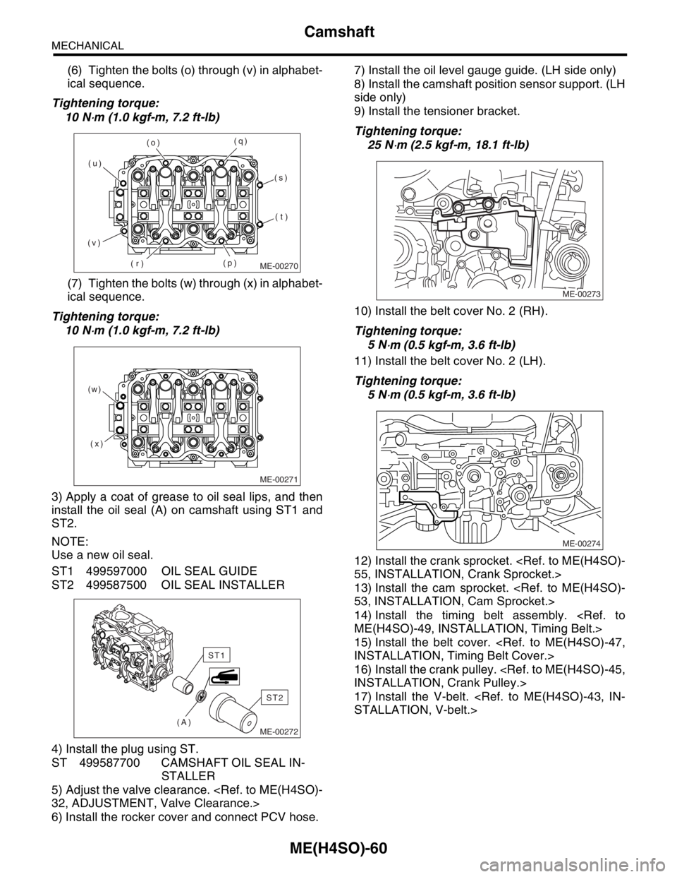
(6) Tighten the bolts (o) through (v) in alphabet-
ical sequence.
Tightening torque:
10 N
⋅m (1.0 kgf-m, 7.2 ft-lb)
(7) Tighten the bolts (w) through (x) in alphabet-
ical sequence.
Tightening torque:
10 N
⋅m (1.0 kgf-m, 7.2 ft-lb)
3) Apply a coat of grease to oil seal lips, and then
install the oil seal (A) on camshaft using ST1 and
ST2.
NOTE:
Use a new oil seal.
ST1 499597000 OIL SEAL GUIDE
ST2 499587500 OIL SEAL INSTALLER
4) Install the plug using ST.
ST 499587700 CAMSHAFT OIL SEAL IN-
STALLER
5) Adjust the valve clearance.
6) Install the rocker cover and connect PCV hose.7) Install the oil level gauge guide. (LH side only)
8) Install the camshaft position sensor support. (LH
side only)
9) Install the tensioner bracket.
Tightening torque:
25 N
⋅m (2.5 kgf-m, 18.1 ft-lb)
10) Install the belt cover No. 2 (RH).
Tightening torque:
5 N
⋅m (0.5 kgf-m, 3.6 ft-lb)
11) Install the belt cover No. 2 (LH).
Tightening torque:
5 N
⋅m (0.5 kgf-m, 3.6 ft-lb)
12) Install the crank sprocket.
13) Install the cam sprocket.
14) Install the timing belt assembly.
15) Install the belt cover.
16) Install the crank pulley.
17) Install the V-belt.
ME-00270
(o)
(r)(q)
(v)(u)
(p)(s)
(t)
ME-00271
(x) (w)
ME-00272(A)
ST2
ST1
ME-00273
ME-00274
Page 952 of 2870
ME(H4SO)-81
MECHANICAL
Cylinder Block
Model with ATF warmer
28) Install the water by-pass pipe for heater.
29) Get a engine oil filter and apply a thin coat of
engine oil to the seal rubber.
30) Install the oil filter by turning it by hand, being
careful not to damage the seal rubber.
Tighten the oil filter 80 mm (3.15 in) or 65 mm
(2.56 in) in diameter by approx. 2/3 — 3/4 rotation
more after the seal rubber of oil filter comes in con-
tact with cylinder block or oil cooler.
Tighten the oil filter 68 mm (2.68 in) in diameter
by approx. 1 rotation more after the seal rubber of
oil filter comes in contact with cylinder block or oil
cooler.
CAUTION:
Do not tighten excessively, or oil may leak.
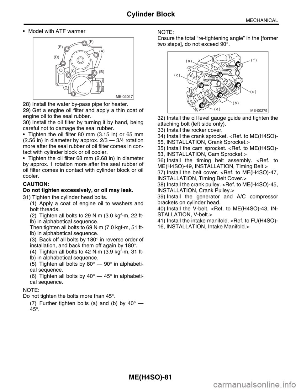
31) Tighten the cylinder head bolts.
(1) Apply a coat of engine oil to washers and
bolt threads.
(2) Tighten all bolts to 29 N⋅m (3.0 kgf-m, 22 ft-
lb) in alphabetical sequence.
Then tighten all bolts to 69 N⋅m (7.0 kgf-m, 51 ft-
lb) in alphabetical sequence.
(3) Back off all bolts by 180° in reverse order of
installation, and back them off again by 180°.
(4) Tighten all bolts to 42 N⋅m (3.9 kgf-m, 31 ft-
lb) in alphabetical sequence.
(5) Tighten all bolts by 80° — 90° in alphabeti-
cal sequence.
(6) Tighten all bolts by 40° — 45° in alphabeti-
cal sequence.
NOTE:
Do not tighten the bolts more than 45°.
(7) Further tighten bolts (a) and (b) by 40° —
45°.NOTE:
Ensure the total “re-tightening angle” in the [former
two steps], do not exceed 90°.
32) Install the oil level gauge guide and tighten the
attaching bolt (left side only).
33) Install the rocker cover.
34) Install the crank sprocket.
35) Install the cam sprocket.
36) Install the timing belt assembly.
37) Install the belt cover.
38) Install the crank pulley.
39) Install the generator and A/C compressor
brackets on cylinder head.
40) Install the V-belt.
41) Install the intake manifold.
ME-02017
(B) (C) (D)(E)(F)
(A)
ME-00279
(c)
(b)(f)
(d) (a)
(e)
Page 1016 of 2870
CO(H4SO)-33
COOLING
Radiator
12) Connect the oil cooler hose. (MT model with oil
cooler)
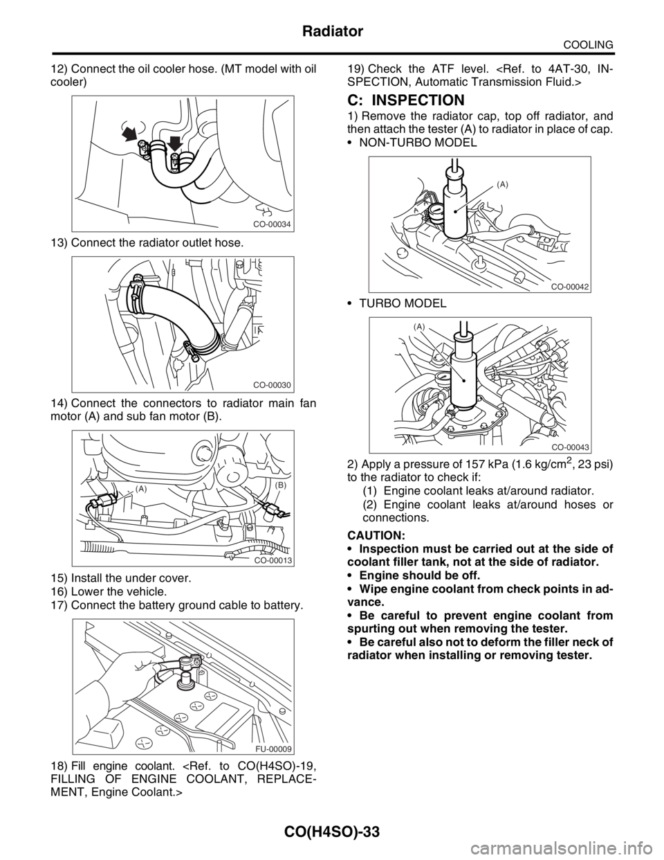
13) Connect the radiator outlet hose.
14) Connect the connectors to radiator main fan
motor (A) and sub fan motor (B).
15) Install the under cover.
16) Lower the vehicle.
17) Connect the battery ground cable to battery.
18) Fill engine coolant.
MENT, Engine Coolant.>19) Check the ATF level.
C: INSPECTION
1) Remove the radiator cap, top off radiator, and
then attach the tester (A) to radiator in place of cap.
NON-TURBO MODEL
TURBO MODEL
2) Apply a pressure of 157 kPa (1.6 kg/cm
2, 23 psi)
to the radiator to check if:
(1) Engine coolant leaks at/around radiator.
(2) Engine coolant leaks at/around hoses or
connections.
CAUTION:
Inspection must be carried out at the side of
coolant filler tank, not at the side of radiator.
Engine should be off.
Wipe engine coolant from check points in ad-
vance.
Be careful to prevent engine coolant from
spurting out when removing the tester.
Be careful also not to deform the filler neck of
radiator when installing or removing tester.
CO-00034
CO-00030
CO-00013
(A)(B)
FU-00009
CO-00042
(A)
CO-00043
(A)
Page 1031 of 2870
LU(H4SO)-3
LUBRICATION
General Description
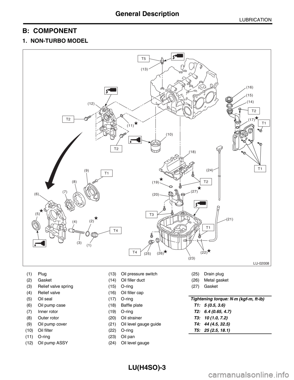
B: COMPONENT
1. NON-TURBO MODEL
(1) Plug (13) Oil pressure switch (25) Drain plug
(2) Gasket (14) Oil filler duct (26) Metal gasket
(3) Relief valve spring (15) O-ring (27) Gasket
(4) Relief valve (16) Oil filler cap
(5) Oil seal (17) O-ringTightening torque: N
⋅m (kgf-m, ft-lb)
(6) Oil pump case (18) Baffle plateT1: 5 (0.5, 3.6)
(7) Inner rotor (19) O-ringT2: 6.4 (0.65, 4.7)
(8) Outer rotor (20) Oil strainerT3: 10 (1.0, 7.2)
(9) Oil pump cover (21) Oil level gauge guideT4: 44 (4.5, 32.5)
(10) Oil filter (22) O-ringT5: 25 (2.5, 18.1)
(11) O-ring (23) Oil pan
(12) Oil pump ASSY (24) Oil level gauge
LU-02008
(12)
(11)
T5
T2
T1
T2
T2
T1
T1
T1
T3
T4
T2
(13)
(9)
(8)
(7)
(6)
(20) (19)
(27) (18)(17) (15)
(14) (16)
(24)
(23) (10)
(25)(26)
(5)
(4)
(3)(2)
(1)
(22)
(21)
T4
Page 1033 of 2870

LU(H4SO)-5
LUBRICATION
General Description
C: CAUTION
Wear working clothing, including a cap, protec-
tive goggles, and protective shoes during opera-
tion.
Remove contamination including dirt and corro-
sion before removal, installation or disassembly.
Keep the disassembled parts in order and pro-
tect them from dust or dirt.
Before removal, installation or disassembly, be
sure to clarify the failure. Avoid unnecessary re-
moval, installation, disassembly, and replacement.
Be careful not to burn yourself, because each
part in the vehicle is hot after running.
Be sure to tighten fasteners including bolts and
nuts to the specified torque.
Place shop jacks or rigid racks at the specified
points.
Before disconnecting electrical connectors of
sensors or units, be sure to disconnect the ground
cable from battery.
(1) Plug (16) Oil pressure switch (33) O-ring
(2) Gasket (17) Oil filler cap (34) Oil filter connector (model without
oil cooler)
(3) Relief valve spring (18) O-ring
(4) Relief valve (19) Oil filler duct (35) Plug (model without oil cooler)
(5) Oil seal (20) O-ring (36) O-ring
(6) Oil pump case (21) Rocker cover
(7) Inner rotor (22) Oil strainerTightening torque: N
⋅m (kgf-m, ft-lb)
(8) Outer rotor (23) GasketT1: 5 (0.5, 3.6)
(9) Oil pump cover (24) Oil level gauge guideT2: 6.4 (0.65, 4.7)
(10) Oil filter (25) Oil panT3: 10 (1.0, 7.0)
(11) Oil cooler connector (model with
oil cooler)(26) Oil level gaugeT4: 44 (4.5, 32.5)
(27) Metal gasketT5: 69 (7.0, 50.9)
(12) Water by-pass pipe (model with oil
cooler)(28) Drain plugT6: 6.4 (0.65, 4.7)
(29) O-ringT7: 25 (2.5, 18.1)
(13) Oil cooler (model with oil cooler) (30) Adapter (1)T8: 44 (4.5, 32.5)
(14) O-ring (31) Adapter (2)T9: 54 (5.5, 40)
(15) Oil pump ASSY (32) Baffle plate
Page 1038 of 2870
LU(H4SO)-10
LUBRICATION
Engine Oil
3. Engine Oil
A: INSPECTION
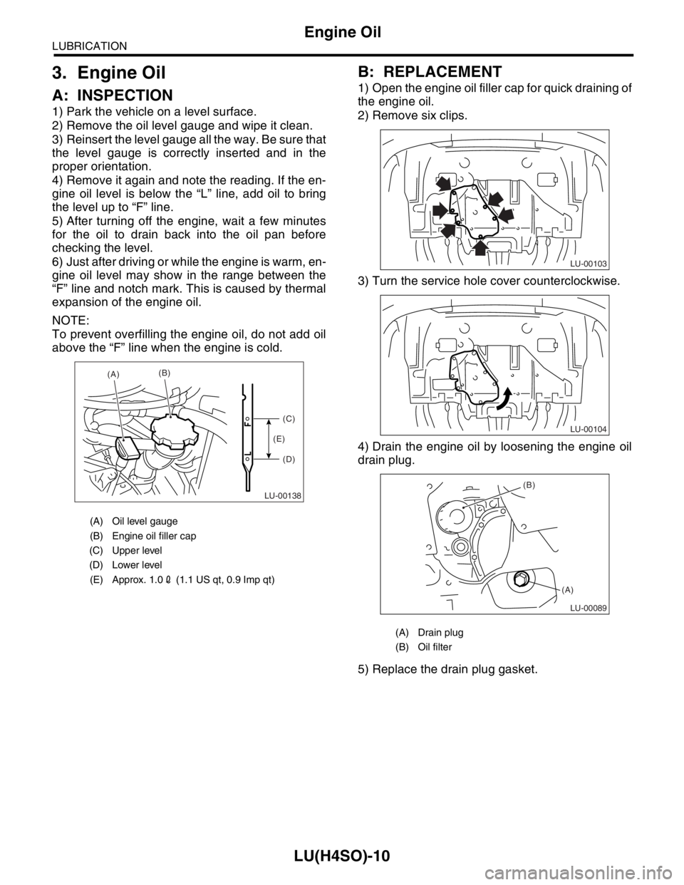
1) Park the vehicle on a level surface.
2) Remove the oil level gauge and wipe it clean.
3) Reinsert the level gauge all the way. Be sure that
the level gauge is correctly inserted and in the
proper orientation.
4) Remove it again and note the reading. If the en-
gine oil level is below the “L” line, add oil to bring
the level up to “F” line.
5) After turning off the engine, wait a few minutes
for the oil to drain back into the oil pan before
checking the level.
6) Just after driving or while the engine is warm, en-
gine oil level may show in the range between the
“F” line and notch mark. This is caused by thermal
expansion of the engine oil.
NOTE:
To prevent overfilling the engine oil, do not add oil
above the “F” line when the engine is cold.
B: REPLACEMENT
1) Open the engine oil filler cap for quick draining of
the engine oil.
2) Remove six clips.
3) Turn the service hole cover counterclockwise.
4) Drain the engine oil by loosening the engine oil
drain plug.
5) Replace the drain plug gasket.
(A) Oil level gauge
(B) Engine oil filler cap
(C) Upper level
(D) Lower level
(E) Approx. 1.02 (1.1 US qt, 0.9 Imp qt)
LU-00138
(A)(B)
(C)
(D) (E)
(A) Drain plug
(B) Oil filter
LU-00103
LU-00104
LU-00089
(B)
(A)
Page 1039 of 2870
LU(H4SO)-11
LUBRICATION
Engine Oil
6) Tighten the engine oil drain plug after draining
engine oil.
Tightening torque:
44 N
⋅m (4.5 kgf-m, 32.5 ft-lb)
7) Install the service hole cover.
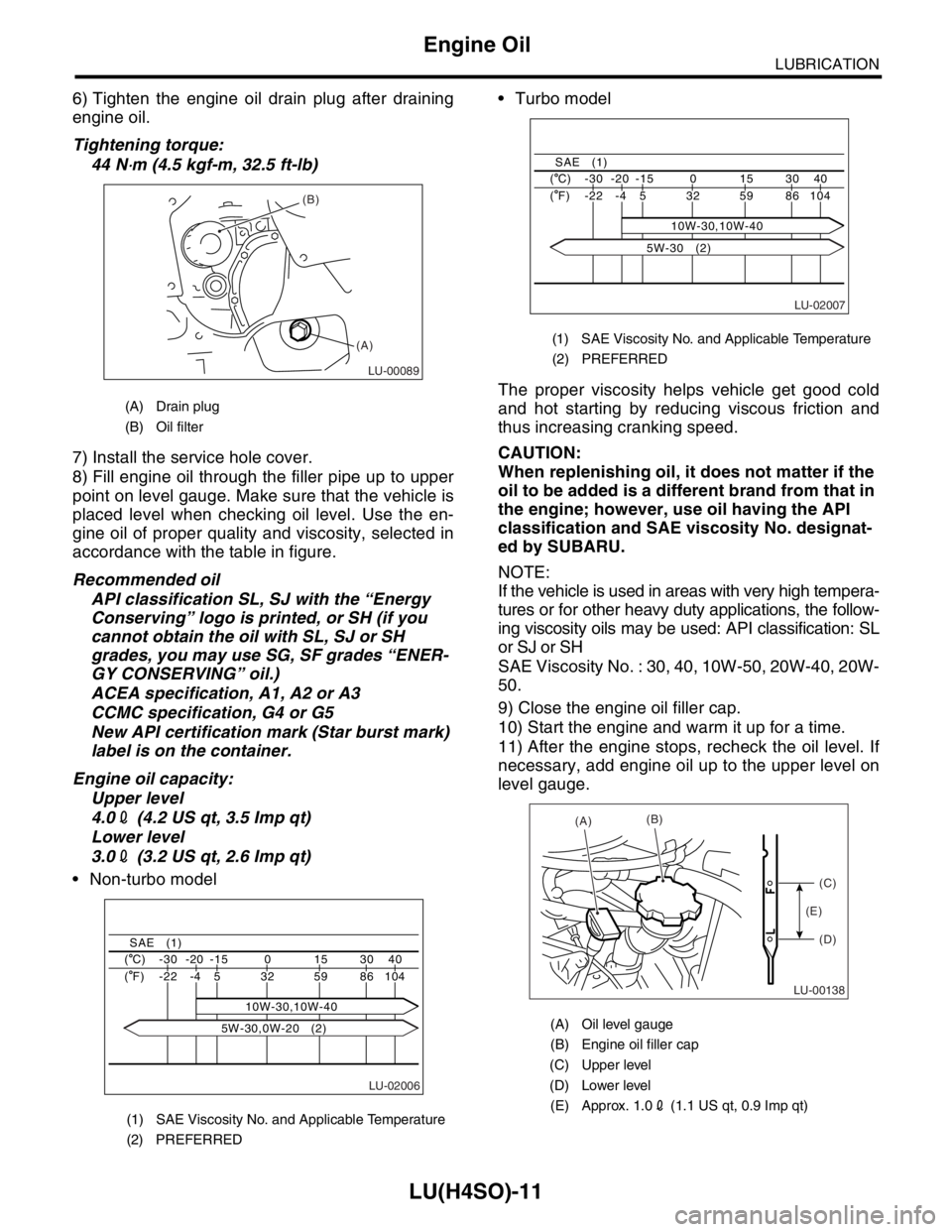
8) Fill engine oil through the filler pipe up to upper
point on level gauge. Make sure that the vehicle is
placed level when checking oil level. Use the en-
gine oil of proper quality and viscosity, selected in
accordance with the table in figure.
Recommended oil
API classification SL, SJ with the “Energy
Conserving” logo is printed, or SH (if you
cannot obtain the oil with SL, SJ or SH
grades, you may use SG, SF grades “ENER-
GY CONSERVING” oil.)
ACEA specification, A1, A2 or A3
CCMC specification, G4 or G5
New API certification mark (Star burst mark)
label is on the container.
Engine oil capacity:
Upper level
4.02 (4.2 US qt, 3.5 Imp qt)
Lower level
3.02 (3.2 US qt, 2.6 Imp qt)
Non-turbo model Turbo model
The proper viscosity helps vehicle get good cold
and hot starting by reducing viscous friction and
thus increasing cranking speed.
CAUTION:
When replenishing oil, it does not matter if the
oil to be added is a different brand from that in
the engine; however, use oil having the API
classification and SAE viscosity No. designat-
ed by SUBARU.
NOTE:
If the vehicle is used in areas with very high tempera-
tures or for other heavy duty applications, the follow-
ing viscosity oils may be used: API classification: SL
or SJ or SH
SAE Viscosity No. : 30, 40, 10W-50, 20W-40, 20W-
50.
9) Close the engine oil filler cap.
10) Start the engine and warm it up for a time.
11) After the engine stops, recheck the oil level. If
necessary, add engine oil up to the upper level on
level gauge.
(A) Drain plug
(B) Oil filter
(1) SAE Viscosity No. and Applicable Temperature
(2) PREFERRED
LU-00089
(B)
(A)
LU-02006
40 30 15 0 -15 -20 -30 ( C)
104 86 59 32
10W-30,10W-40 5 -4 -22 ( F)
SAE (1)
5W-30,0W-20 (2)
(1) SAE Viscosity No. and Applicable Temperature
(2) PREFERRED
(A) Oil level gauge
(B) Engine oil filler cap
(C) Upper level
(D) Lower level
(E) Approx. 1.02 (1.1 US qt, 0.9 Imp qt)
LU-02007
40 30 15 0 -15 -20 -30 ( C)
104 86 59 32 5 -4 -22 ( F)
SAE (1)
10W-30,10W-40
5W-30 (2)
LU-00138
(A)(B)
(C)
(D) (E)
Page 1051 of 2870
LU(H4SO)-23
LUBRICATION
Engine Oil Filter
8. Engine Oil Filter
A: REMOVAL
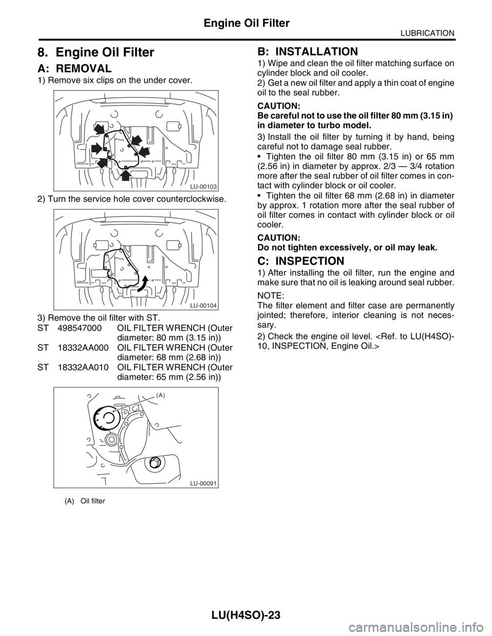
1) Remove six clips on the under cover.
2) Turn the service hole cover counterclockwise.
3) Remove the oil filter with ST.
ST 498547000 OIL FILTER WRENCH (Outer
diameter: 80 mm (3.15 in))
ST 18332AA000 OIL FILTER WRENCH (Outer
diameter: 68 mm (2.68 in))
ST 18332AA010 OIL FILTER WRENCH (Outer
diameter: 65 mm (2.56 in))
B: INSTALLATION
1) Wipe and clean the oil filter matching surface on
cylinder block and oil cooler.
2) Get a new oil filter and apply a thin coat of engine
oil to the seal rubber.
CAUTION:
Be careful not to use the oil filter 80 mm (3.15 in)
in diameter to turbo model.
3) Install the oil filter by turning it by hand, being
careful not to damage seal rubber.
Tighten the oil filter 80 mm (3.15 in) or 65 mm
(2.56 in) in diameter by approx. 2/3 — 3/4 rotation
more after the seal rubber of oil filter comes in con-
tact with cylinder block or oil cooler.
Tighten the oil filter 68 mm (2.68 in) in diameter
by approx. 1 rotation more after the seal rubber of
oil filter comes in contact with cylinder block or oil
cooler.
CAUTION:
Do not tighten excessively, or oil may leak.
C: INSPECTION
1) After installing the oil filter, run the engine and
make sure that no oil is leaking around seal rubber.
NOTE:
The filter element and filter case are permanently
jointed; therefore, interior cleaning is not neces-
sary.
2) Check the engine oil level.
(A) Oil filter
LU-00103
LU-00104
LU-00091
(A)