Page 2377 of 2870
4AT-64
AUTOMATIC TRANSMISSION
Control Valve Body
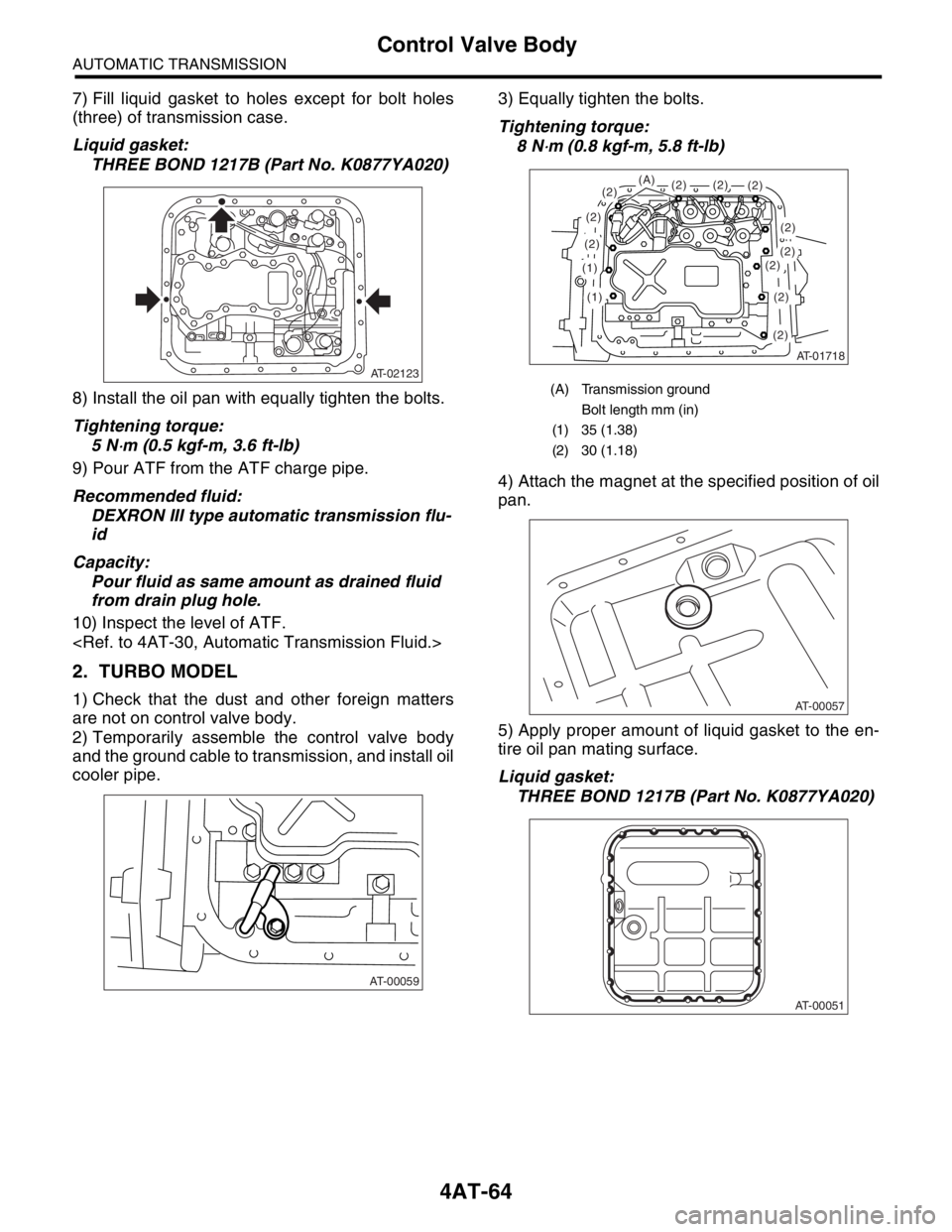
7) Fill liquid gasket to holes except for bolt holes
(three) of transmission case.
Liquid gasket:
THREE BOND 1217B (Part No. K0877YA020)
8) Install the oil pan with equally tighten the bolts.
Tightening torque:
5 N
⋅m (0.5 kgf-m, 3.6 ft-lb)
9) Pour ATF from the ATF charge pipe.
Recommended fluid:
DEXRON III type automatic transmission flu-
id
Capacity:
Pour fluid as same amount as drained fluid
from drain plug hole.
10) Inspect the level of ATF.
2. TURBO MODEL
1) Check that the dust and other foreign matters
are not on control valve body.
2) Temporarily assemble the control valve body
and the ground cable to transmission, and install oil
cooler pipe.3) Equally tighten the bolts.
Tightening torque:
8 N
⋅m (0.8 kgf-m, 5.8 ft-lb)
4) Attach the magnet at the specified position of oil
pan.
5) Apply proper amount of liquid gasket to the en-
tire oil pan mating surface.
Liquid gasket:
THREE BOND 1217B (Part No. K0877YA020)
AT-02123
AT-00059
(A) Transmission ground
Bolt length mm (in)
(1) 35 (1.38)
(2) 30 (1.18)
AT-01718
(1)
(1)
(2)
(2)
(2)(2)
(2)
(2)(2)(2)(2)
(2)
(2)
(A)
AT-00057
AT-00051
Page 2378 of 2870
4AT-65
AUTOMATIC TRANSMISSION
Control Valve Body
6) Fill liquid gasket to holes except for bolt holes
(three) of transmission case.
Liquid gasket:
THREE BOND 1217B (Part No. K0877YA020)
7) Install the oil pan with equally tighten the bolts.
Tightening torque:
5 N
⋅m (0.5 kgf-m, 3.6 ft-lb)
8) Pour ATF from the ATF charge pipe.
Recommended fluid:
DEXRON III type automatic transmission flu-
id
Capacity:
Pour fluid as same amount as drained fluid
from drain plug hole.
9) Bleed the air of control valve.
Air Bleeding of Control Valve.>
10) Check the ATF level.
matic Transmission Fluid.>
11) Execute the learning control promotion.
to 4AT(H4DOTC)-17, FACILITATION OF LEARN-
ING CONTROL, OPERATION, Subaru Select
Monitor.>
C: DISASSEMBLY
Non-turbo model only
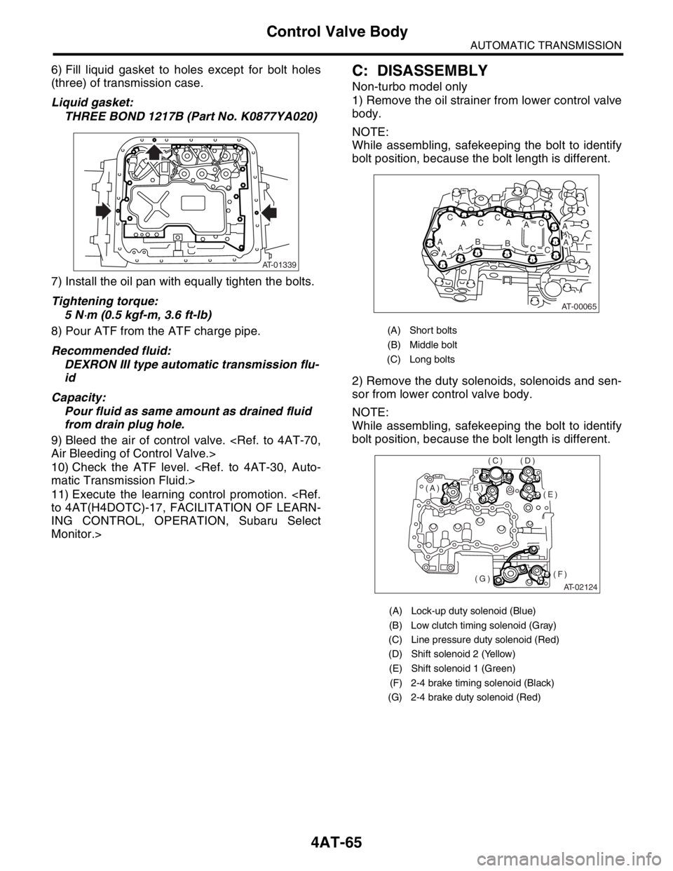
1) Remove the oil strainer from lower control valve
body.
NOTE:
While assembling, safekeeping the bolt to identify
bolt position, because the bolt length is different.
2) Remove the duty solenoids, solenoids and sen-
sor from lower control valve body.
NOTE:
While assembling, safekeeping the bolt to identify
bolt position, because the bolt length is different.
AT-01339
(A) Short bolts
(B) Middle bolt
(C) Long bolts
(A) Lock-up duty solenoid (Blue)
(B) Low clutch timing solenoid (Gray)
(C) Line pressure duty solenoid (Red)
(D) Shift solenoid 2 (Yellow)
(E) Shift solenoid 1 (Green)
(F) 2-4 brake timing solenoid (Black)
(G) 2-4 brake duty solenoid (Red)
AT-00065
A
ABAA
AC
ACC
AB
AC
CC
AT-02124
(E)
(F)(G)
(D)(C)
(B)(A)
Page 2385 of 2870
4AT-72
AUTOMATIC TRANSMISSION
Shift Solenoids, Duty Solenoids and ATF Temperature Sensor
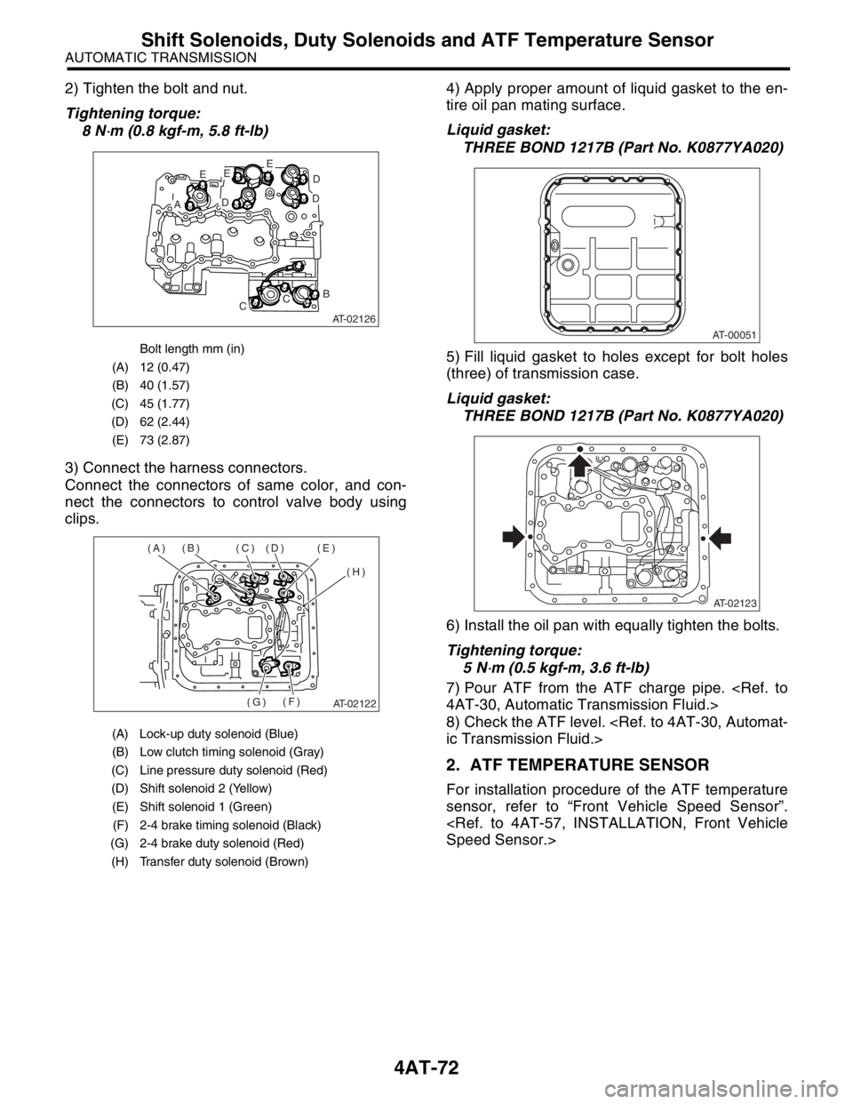
2) Tighten the bolt and nut.
Tightening torque:
8 N
⋅m (0.8 kgf-m, 5.8 ft-lb)
3) Connect the harness connectors.
Connect the connectors of same color, and con-
nect the connectors to control valve body using
clips.4) Apply proper amount of liquid gasket to the en-
tire oil pan mating surface.
Liquid gasket:
THREE BOND 1217B (Part No. K0877YA020)
5) Fill liquid gasket to holes except for bolt holes
(three) of transmission case.
Liquid gasket:
THREE BOND 1217B (Part No. K0877YA020)
6) Install the oil pan with equally tighten the bolts.
Tightening torque:
5 N
⋅m (0.5 kgf-m, 3.6 ft-lb)
7) Pour ATF from the ATF charge pipe.
4AT-30, Automatic Transmission Fluid.>
8) Check the ATF level.
ic Transmission Fluid.>
2. ATF TEMPERATURE SENSOR
For installation procedure of the ATF temperature
sensor, refer to “Front Vehicle Speed Sensor”.
Speed Sensor.>
Bolt length mm (in)
(A) 12 (0.47)
(B) 40 (1.57)
(C) 45 (1.77)
(D) 62 (2.44)
(E) 73 (2.87)
(A) Lock-up duty solenoid (Blue)
(B) Low clutch timing solenoid (Gray)
(C) Line pressure duty solenoid (Red)
(D) Shift solenoid 2 (Yellow)
(E) Shift solenoid 1 (Green)
(F) 2-4 brake timing solenoid (Black)
(G) 2-4 brake duty solenoid (Red)
(H) Transfer duty solenoid (Brown)
AT-02126
E
AD
EE
D
D
B
CC
AT-02122
(A) (B) (C) (D) (E)
(H)
(F)
(G)
AT-00051
AT-02123
Page 2389 of 2870
4AT-76
AUTOMATIC TRANSMISSION
ATF Filter
21.ATF Filter
A: REMOVAL
NOTE:
The ATF filter is maintenance free.
1) Lift-up the vehicle.
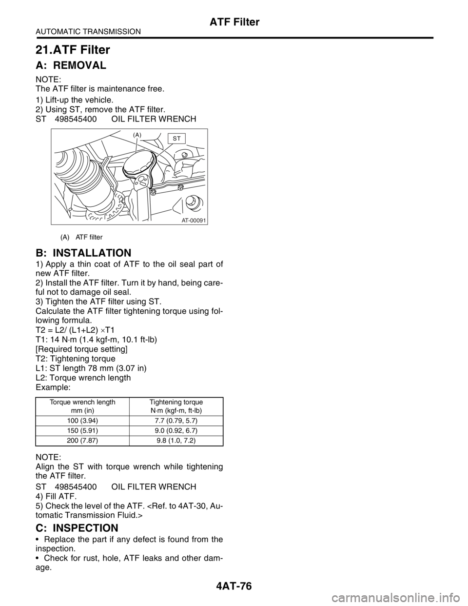
2) Using ST, remove the ATF filter.
ST 498545400 OIL FILTER WRENCH
B: INSTALLATION
1) Apply a thin coat of ATF to the oil seal part of
new ATF filter.
2) Install the ATF filter. Turn it by hand, being care-
ful not to damage oil seal.
3) Tighten the ATF filter using ST.
Calculate the ATF filter tightening torque using fol-
lowing formula.
T2 = L2/ (L1+L2) ×T1
T1: 14 N⋅m (1.4 kgf-m, 10.1 ft-lb)
[Required torque setting]
T2: Tightening torque
L1: ST length 78 mm (3.07 in)
L2: Torque wrench length
Example:
NOTE:
Align the ST with torque wrench while tightening
the ATF filter.
ST 498545400 OIL FILTER WRENCH
4) Fill ATF.
5) Check the level of the ATF.
tomatic Transmission Fluid.>
C: INSPECTION
Replace the part if any defect is found from the
inspection.
Check for rust, hole, ATF leaks and other dam-
age.
(A) ATF filter
Torque wrench length
mm (in)Tightening torque
N⋅m (kgf-m, ft-lb)
100 (3.94) 7.7 (0.79, 5.7)
150 (5.91) 9.0 (0.92, 6.7)
200 (7.87) 9.8 (1.0, 7.2)
AT-00091
(A)ST
Page 2401 of 2870
4AT-88
AUTOMATIC TRANSMISSION
Oil Charger Pipe
27.Oil Charger Pipe
A: REMOVAL
1) Remove the air cleaner case. (Non-turbo mod-
el).
Case.>
2) Remove the intercooler. (Turbo model)
er.>
3) Remove the ATF charger pipe, and then remove
the O-ring from flange side.
Model without ATF warmer
Model with ATF warmer
B: INSTALLATION
1) Install the ATF charger pipe with a new O-ring.
Tightening torque:
41 N
⋅m (4.2 kgf-m, 30.4 ft-lb)
Model without ATF warmer
Model with ATF warmer
2) Install the air cleaner case. (Non-turbo model).
Case.>
3) Install the intercooler. (Turbo model)
cooler.>
C: INSPECTION
Make sure the ATF charger pipe is not deformed or
damaged.
(A) ATF level gauge
(B) ATF charger pipe
(A) ATF level gauge
(B) ATF charger pipe
AT-00808
(A)
(B)
AT-01872
(B)
(A)
(A) ATF level gauge
(B) ATF charger pipe
(A) ATF level gauge
(B) ATF charger pipe
AT-00808
(A)
(B)
AT-01872
(B)
(A)
Page 2464 of 2870
4AT(H4SO)-5
AUTOMATIC TRANSMISSION (DIAGNOSTIC)
General Description
3. General Description
A: CAUTION
Supplemental Restraint System “Airbag”
The airbag system wiring harness is routed near
the transmission control module (TCM).
CAUTION:
All airbag system wiring harness and con-
nectors are colored yellow. Do not use an elec-
trical test equipment on these circuit.
Be careful not to damage the airbag system wir-
ing harness when performing diagnostics and ser-
vicing the TCM.
Measurement
When measuring the voltage and resistance of
ECM, TCM or each sensor, use a tapered pin with
diameter of less than 0.64 mm (0.025 in) in order to
avoid poor contact. Do not insert the pin more than
0.65 mm (0.256 in).
B: INSPECTION
1. BATTERY
Measure the battery voltage and specific gravity of
electrolyte.
Standard voltage: 12 V or more
Specific gravity: Above 1.260
2. TRANSMISSION GROUND
Make sure that the ground terminal bolt is tightened
securely.
Chassis side
Tightening torque:
13 N
⋅m (1.3 kgf-m, 9.4 ft-lb)
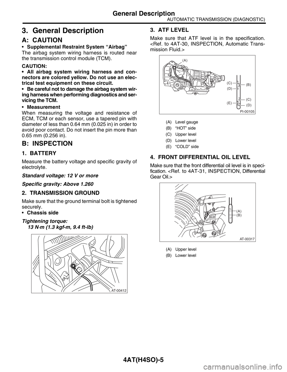
3. ATF LEVEL
Make sure that ATF level is in the specification.
mission Fluid.>
4. FRONT DIFFERENTIAL OIL LEVEL
Make sure that the front differential oil level is in speci-
fication.
Gear Oil.>
AT-00412
(A) Level gauge
(B) “HOT” side
(C) Upper level
(D) Lower level
(E) “COLD” side
(A) Upper level
(B) Lower level
PI-00105
COLD
LFHOT LF
(A)
(C)
(D)
(C)
(D)
(E)
(B)
AT-00317
(A)
(B)
LF
Page 2569 of 2870

4AT(H4SO)-110
AUTOMATIC TRANSMISSION (DIAGNOSTIC)
Symptom Related Diagnostic
15.Symptom Related Diagnostic
A: INSPECTION
Symptom Problem parts
Starter does not rotate when select lever is in “P” or “N” range;
starter rotates when select lever is in “R”, “D”, “3” or “2” range. Inhibitor switch
Select cable
Select lever
Starter motor and harness
Abnormal noise when select lever is in “P” or “N” range. Strainer
Transfer duty solenoid
Oil pump
Drive plate
ATF level too high or too low
Hissing noise occurs during standing start. Strainer
ATF level too high or too low
Noise occurs while driving in “D1”. Final gear
Planetary gear
Reduction gear
Differential gear oil level too high or too low Noise occurs while driving in “D2”.
Noise occurs while driving in “D3”. Final gear
Low & reverse brake
Reduction gear
Differential gear oil level too high or too low
Noise occurs while driving in “D4”. Final gear
Low & reverse brake
Planetary gear
Reduction gear
Differential gear oil level too high or too low
Engine stalls while shifting from “1” range to another. Control valve
Lock-up damper
Engine performance
Input shaft
Vehicle moves when select lever is in “N” range. Low clutch
Shock occurs when select lever is moved from “N” to “D” range.TCM
Harness
Control valve
ATF deterioration
Excessive time lag occurs when select lever is moved from “N”
to “D” range. Control valve
Low clutch
Line pressure duty solenoid
Seal ring
Front gasket transmission case
Shock occurs when select lever is moved from “N” to “R” range.TCM
Harness
Control valve
ATF deterioration
Excessive time lag occurs when select lever is moved from “N”
to “R” range. Control valve
Low & reverse clutch
Reverse clutch
Line pressure duty solenoid
Seal ring
Front gasket transmission case
Vehicle does not start in any shift range (engine stalls). Parking brake mechanism
Planetary gear
Page 2570 of 2870

4AT(H4SO)-111
AUTOMATIC TRANSMISSION (DIAGNOSTIC)
Symptom Related Diagnostic
Vehicle does not start in any shift range (engine revving up). Strainer
Line pressure duty solenoid
Control valve
Drive pinion
Hypoid gear
Axle shaft
Differential gear
Oil pump
Input shaft
Output shaft
Planetary gear
Drive plate
ATF level too low
Front gasket transmission case
Vehicle does not start in “R” range only (engine revving up). Select cable
Select lever
Control valve
Low & reverse clutch
Reverse clutch
Vehicle does not start in “R” range only (engine stalls). Low clutch
2-4 brake
Planetary gear
Parking brake mechanism
Vehicle does not start in “D”, “3” range only (engine revving up). Low clutch
One-way clutch
Vehicle does not start in “D”, “3” or “2” range only (engine rev-
ving up). Low clutch
Vehicle does not start in “D”, “3” or “2” range only (engine stalls). Reverse clutch
Vehicle starts in “R” range only (engine revving up). Control valve
Acceleration during standing starts is poor (high stall rpm). Control valve
Low clutch
Reverse clutch
ATF level too low
Front gasket transmission case
Differential gear oil level too high or too low
Acceleration during standing starts is poor (low stall rpm). Oil pump
Torque converter one-way clutch
Engine performance
Acceleration is poor when select lever is in “D”, “3” or “2” range
(normal stall rpm).TCM
Control valve
High clutch
2-4 brake
Planetary gear
Acceleration is poor when select lever is in “R” (normal stall rpm). Control valve
High clutch
2-4 brake
Planetary gear
No shift occurs from 1st to 2nd gear.TCM
Rear vehicle speed sensor
Front vehicle speed sensor
Throttle position sensor
Shift solenoid 1
Control valve
2-4 brake
No shift occurs from 2nd to 3rd gear.TCM
Control valve
High clutch
Shift solenoid 2 Symptom Problem parts