2004 SUBARU FORESTER light
[x] Cancel search: lightPage 591 of 2870
CC(H4SO)-23
CRUISE CONTROL SYSTEM (DIAGNOSTIC)
Diagnostic Procedure with Symptom
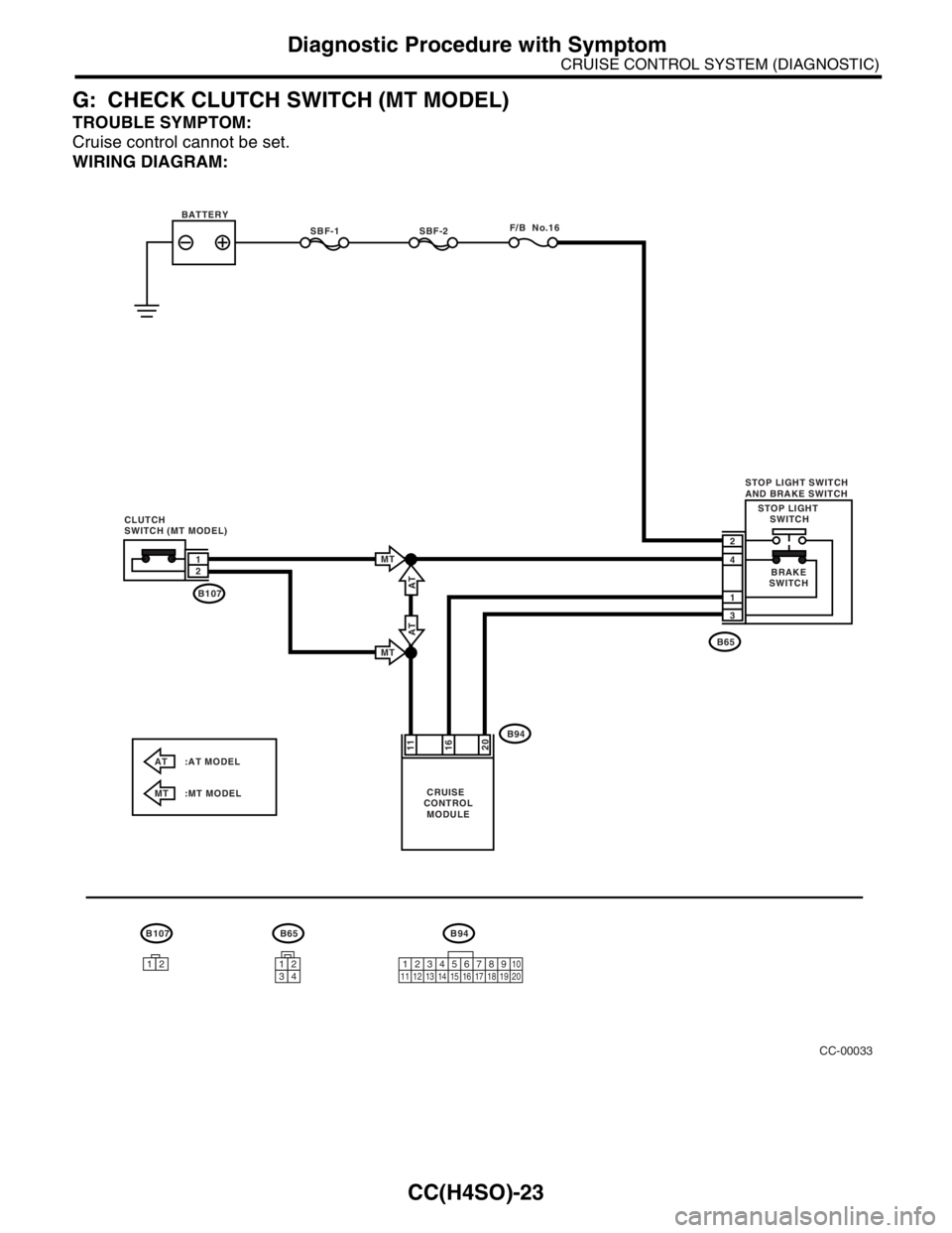
G: CHECK CLUTCH SWITCH (MT MODEL)
TROUBLE SYMPTOM:
Cruise control cannot be set.
WIRING DIAGRAM:
CC-00033
B107B94B65
AT :AT MODEL
MT :MT MODEL
1212345678910
11 12 13 14 15 16 17 18 19 20
BATTERY
CRUISE
CONTROL
MODULE
SBF-1SBF-2F/B No.16
CLUTCH
SWITCH (MT MODEL)
1
2
B65
B94
B107STOP LIGHT SWITCH
AND BRAKE SWITCH
BRAKE
SWITCH STOP LIGHT
SWITCH
4
3
1
2
2011
16
AT
MT
MT
AT
1234
Page 592 of 2870

CC(H4SO)-24
CRUISE CONTROL SYSTEM (DIAGNOSTIC)
Diagnostic Procedure with Symptom
Step Check Yes No
1 CHECK CLUTCH SWITCH CIRCUIT.
1) Turn the ignition switch to OFF.
2) Disconnect the clutch switch harness con-
nector.
3) Turn the ignition switch to ON.
4) Turn the cruise control main switch to ON.
5) Measure the voltage between harness con-
nector terminal and chassis ground.
Connector & terminal
(B107) No. 2 (+) — Chassis ground (
−):Is the voltage more than 10 V? Go to step 2.Check the harness
for open or short
between clutch
switch and cruise
control module.
2 CHECK CLUTCH SWITCH CIRCUIT.
1) Turn the cruise control main switch and
ignition switch OFF.
2) Disconnect the stop light switch and brake
switch harness connector.
3) Measure the resistance between clutch
switch harness connector terminal and stop
light switch and brake switch harness connec-
tor terminal.
Connector & terminal
(B107) No. 1 — (B65) No. 4:Is the resistance less than 10
Ω?Go to step 3.Repair the har-
ness.
3 CHECK CLUTCH SWITCH.
Remove and check the clutch switch.
cuit is OK.Replace the clutch
switch.
Page 607 of 2870
FUJI HEAVY INDUSTRIES LTD. G8080GE7
2004 FORESTER SERVICE MANUAL QUICK REFERENCE INDEX
BODY SECTION
This service manual has been prepared
to provide SUBARU service personnel
with the necessary information and data
for the correct maintenance and repair
of SUBARU vehicles.
This manual includes the procedures
for maintenance, disassembling, reas-
sembling, inspection and adjustment of
components and diagnostics for guid-
ance of experienced mechanics.
Please peruse and utilize this manual
fully to ensure complete repair work for
satisfying our customers by keeping
their vehicle in optimum condition.
When replacement of parts during
repair work is needed, be sure to use
SUBARU genuine parts.
All information, illustration and specifi-
cations contained in this manual are
based on the latest product information
available at the time of publication
approval.HVAC SYSTEM
(HEATER, VENTILATOR AND A/C)AC
HVAC SYSTEM (AUTO A/C)
(DIAGNOSTIC)AC
AIRBAG SYSTEM AB
AIRBAG SYSTEM (DIAGNOSTIC) AB
SEAT BELT SYSTEM SB
LIGHTING SYSTEM LI
WIPER AND WASHER SYSTEM WW
ENTERTAINMENT ET
COMMUNICATION SYSTEM COM
GLASS/WINDOW/MIRROR GW
BODY STRUCTURE BS
INSTRUMENTATION/DRIVER INFO IDI
SEAT SE
SECURITY AND LOCK SL
SUNROOF/T-TOP/CONVERTIBLE TOP
(SUNROOF)SR
EXTERIOR/INTERIOR TRIM EI
EXTERIOR BODY PANEL EB
Page 611 of 2870
FUJI HEAVY INDUSTRIES LTD. G8080GE7
2004 FORESTER SERVICE MANUAL QUICK REFERENCE INDEX
BODY SECTION
This service manual has been prepared
to provide SUBARU service personnel
with the necessary information and data
for the correct maintenance and repair
of SUBARU vehicles.
This manual includes the procedures
for maintenance, disassembling, reas-
sembling, inspection and adjustment of
components and diagnostics for guid-
ance of experienced mechanics.
Please peruse and utilize this manual
fully to ensure complete repair work for
satisfying our customers by keeping
their vehicle in optimum condition.
When replacement of parts during
repair work is needed, be sure to use
SUBARU genuine parts.
All information, illustration and specifi-
cations contained in this manual are
based on the latest product information
available at the time of publication
approval.HVAC SYSTEM
(HEATER, VENTILATOR AND A/C)AC
HVAC SYSTEM (AUTO A/C)
(DIAGNOSTIC)AC
AIRBAG SYSTEM AB
AIRBAG SYSTEM (DIAGNOSTIC) AB
SEAT BELT SYSTEM SB
LIGHTING SYSTEM LI
WIPER AND WASHER SYSTEM WW
ENTERTAINMENT ET
COMMUNICATION SYSTEM COM
GLASS/WINDOW/MIRROR GW
BODY STRUCTURE BS
INSTRUMENTATION/DRIVER INFO IDI
SEAT SE
SECURITY AND LOCK SL
SUNROOF/T-TOP/CONVERTIBLE TOP
(SUNROOF)SR
EXTERIOR/INTERIOR TRIM EI
EXTERIOR BODY PANEL EB
Page 614 of 2870

CC(H4DOTC 2.5)-2
CRUISE CONTROL SYSTEM (DIAGNOSTIC)
Basic Diagnostic Procedure
1. Basic Diagnostic Procedure
A: PROCEDURE
Step Check Yes No
1 CHECK MALFUNCTION INDICATOR LIGHT.
Check the malfunction indicator light illumi-
nates.Does the malfunction indicator
light illuminate?Go to step 5.Go to step 2.
2 CHECK CRUISE INDICATOR LIGHT.
Check the cruise indicator light blinks.Does the cruise indicator light
blink?Go to step 5.Go to step 3.
3 CHECK CRUISE CONTROL MAIN SWITCH
OPERATION.
Check the cruise control main switch opera-
tion. (Check the cruise indicator light illumi-
nates.)Is the cruise control main
switch set to on? (Does the
cruise indicator light illumi-
nate?)Go to step 4.Go to symptom 1.
10, SYMPTOM
CHART, Diagnos-
tic Procedure with
Symptom.>
4 CHECK CRUISE CONTROL SET OPERA-
TION.
Check the cruise control set operation.Can the cruise control be set
while driving at 40 km/h (25
MPH)?Go to step 6.Go to step 5.
5 PERFORM CRUISE CONTROL CANCEL
CONDITION DIAGNOSIS.
Perform the cruise control cancel condition
diagnosis.Are any DTC indicated? Go to “List of
DTC”.
13, List of Diag-
nostic Trouble
Code (DTC).>Go to symptom 2.
10, SYMPTOM
CHART, Diagnos-
tic Procedure with
Symptom.>
6 CHECK VEHICLE SPEED IS HELD WITHIN
SET SPEED.
Make sure the vehicle speed is held within set
speed.Is the vehicle speed held within
set speed ±3 km/h (±2 MPH)?
(Make an inspection on a level
road.)Go to step 7.Go to symptom 3.
10, SYMPTOM
CHART, Diagnos-
tic Procedure with
Symptom.>
7 CHECK RESUME/ACCEL OPERATION.
Check the RESUME/ACCEL switch operation.Does the vehicle speed
increase or return to set speed
after RESUME/ACCEL switch
has been pressed?Go to step 8.Go to symptom 4.
10, SYMPTOM
CHART, Diagnos-
tic Procedure with
Symptom.>
8 CHECK SET/COAST OPERATION.
Check the SET/COAST switch operation.Does the vehicle speed
decrease after SET/COAST
switch has been pressed?Go to step 9.Go to symptom 5.
10, SYMPTOM
CHART, Diagnos-
tic Procedure with
Symptom.>
9 CHECK CANCEL OPERATION.
Check the CANCEL switch operation.Is the cruise control released
after CANCEL switch has been
pressed?Go to step 10.Go to symptom 6.
10, SYMPTOM
CHART, Diagnos-
tic Procedure with
Symptom.>
Page 617 of 2870
CC(H4DOTC 2.5)-5
CRUISE CONTROL SYSTEM (DIAGNOSTIC)
Electrical Components Location
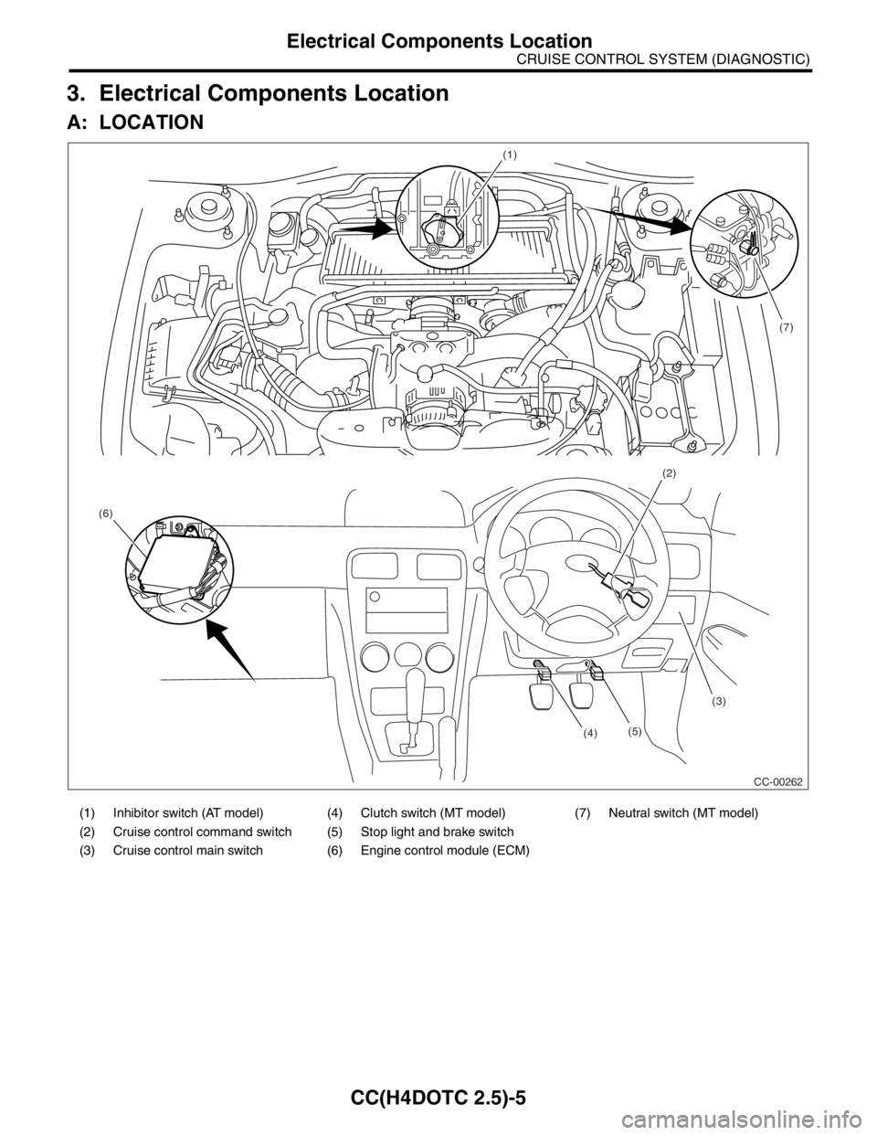
3. Electrical Components Location
A: LOCATION
(1) Inhibitor switch (AT model) (4) Clutch switch (MT model) (7) Neutral switch (MT model)
(2) Cruise control command switch (5) Stop light and brake switch
(3) Cruise control main switch (6) Engine control module (ECM)
(1)
(2)
(3)
(4) (6)(7)
CC-00262 (5)
Page 618 of 2870
CC(H4DOTC 2.5)-6
CRUISE CONTROL SYSTEM (DIAGNOSTIC)
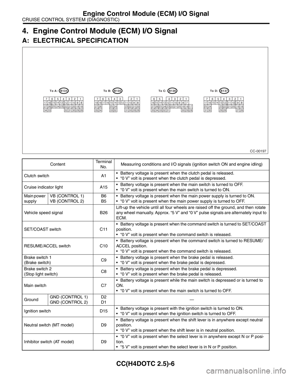
Engine Control Module (ECM) I/O Signal
4. Engine Control Module (ECM) I/O Signal
A: ELECTRICAL SPECIFICATION
ContentTe r m i n a l
No.Measuring conditions and I/O signals (ignition switch ON and engine idling)
Clutch switch A1 Battery voltage is present when the clutch pedal is released.
“0 V” volt is present when the clutch pedal is depressed.
Cruise indicator light A15 Battery voltage is present when the main switch is turned to OFF.
“0 V” volt is present when the main switch is turned to ON.
Main power
supplyVB (CONTROL 1)
VB (CONTROL 2)B6
B5 Battery voltage is present when the main power supply is turned to ON.
“0 V” volt is present when the main power supply is turned to OFF.
Vehicle speed signal B26Lift-up the vehicle until all four wheels are raised off the ground, and then rotate
any wheel manually. Approx. “5 V” and “0 V” pulse signals are alternately input to
ECM.
SET/COAST switch C11 Battery voltage is present when the command switch is turned to SET/COAST
position.
“0 V” volt is present when the command switch is released.
RESUME/ACCEL switch C10 Battery voltage is present when the command switch is turned to RESUME/
ACCEL position.
“0 V” volt is present when the command switch is released.
Brake switch 1
(Brake switch)C9 Battery voltage is present when the brake pedal is released.
“0 V” volt is present when the brake pedal is depressed.
Brake switch 2
(Stop light switch)C8 Battery voltage is present when the brake pedal is depressed.
“0 V” volt is present when the brake pedal is released.
Main switch C7 Battery voltage is present while the main switch is depressed or is turned to
ON.
“0 V” volt is present when the main switch is turned to OFF.
GroundGND (CONTROL 1)
GND (CONTROL 2)D2
D1—
Ignition switch D15 Battery voltage is present with the ignition switch is turned to ON.
“0 V” volt is present when the ignition switch is turned to OFF.
Neutral switch (MT model) D9 Battery voltage is present when the shift lever is in anywhere except neutral
position.
“0 V” volt is present when the shift lever is in neutral position.
Inhibitor switch (AT model) D9 “0 V” volt is present when the select lever is in anywhere except N or P posi-
tion.
“5 V” volt is present when the select lever is in N or P position.
CC-00197
B134
9
30 29 28 32 3120 19 18 22 2110 12 1114
24
34 3327 2617 16123456713
23 15
258
B135
9
30 29 28
323120 22 2110 12 1114
24
35
3327 2617 16123456713
23 15
258
B136
9
30 29 28
32 3120 19 18 22 2110 12 1114
24
34 3327 261612345613
23 15
258
B137
9
29 2820 19 18 22
2110 12
1114
2417 16123456713
23 15
2581819
34
7173530 3127 26
To D: To C: To B: To A:
Page 621 of 2870

CC(H4DOTC 2.5)-9
CRUISE CONTROL SYSTEM (DIAGNOSTIC)
Subaru Select Monitor
9) If the cruise speed is canceled itself (without do-
ing any cancel operations), DTC will appear on se-
lect monitor display after {Cancel Code(s) Display}
is selected on the Engine Diagnosis display screen
and [YES] key is pressed.
CAUTION:
DTC will also appear when cruise cancel is ef-
fected by driver. Do not confuse.
Have a co-worker ride in the vehicle to assist
in diagnosis during driving.
NOTE:
DTC will be cleared by turning the ignition switch or
cruise control main switch to OFF.
3. REAL-TIME DIAGNOSIS
1) Connect the select monitor.
2) Turn the ignition switch and cruise control main
switch to ON.
3) Turn the Subaru Select Monitor switch to ON.
4) On the «Main Menu» display screen, select the
{2. Each System Check} and press [YES] key.
5) On the «System Selection» display screen, se-
lect the {Engine} and press [YES] key.
6) Press the [YES] key after the information of en-
gine type displayed.
7) On the «Engine Diagnosis» display screen, se-
lect the {Current Data Display & Save} and press
[YES] key.
8) Make sure that normal indication is displayed
when controls are operated as indicated below:
Depress/release the brake pedal. (Stop light
switch and brake switch turn ON.)
Turn ON the “SET/COAST” switch.
Turn ON the “RESUME/ACCEL” switch.
Turn ON the “CANCEL” switch. (The “SET/
COAST” and “RESUME/ACCEL” switch are turned
ON at same time.)
Depress/release the clutch pedal.
Set the shift lever to except for neutral position.
NOTE:
For detailed operation procedure, refer to the “SUB-
ARU SELECT MONITOR OPERATION MANUAL.”
For details concerning DTCs, refer to the “List of
Diagnostic Trouble Code (DTC).”
Code (DTC).>