Page 506 of 2870
EI-30
EXTERIOR/INTERIOR TRIM
Rear Bumper
6. Rear Bumper
A: REMOVAL
1) Disconnect the ground cable from battery.
2) Remove the bolts and clips.
3) Remove the clips from bumper and bracket.
4) Remove the rear combination light assemblies
from each side.
Combination Light Assembly.>
5) Remove the two clips from each side.
6) Remove the floor box.7) Remove the rear skirt trim.
8) Remove the bolt to remove bracket from
bumper.
9) Loosen the four nuts to remove rear bumper.
10) Disengage the clips to remove bumper upper
beam.
B: INSTALLATION
Install in the reverse order of removal.
Tightening torque:
Refer to COMPONENT in General Descrip-
tion.
General Description.>
C: REPAIR
Refer to front bumper repair.
MOVAL, Front Bumper.>
EI-00043
EI-00044
EI-00045
EI-00047
EI-00046
EI-00048
Page 510 of 2870

EI-34
EXTERIOR/INTERIOR TRIM
Side Garnish
10.Side Garnish
A: REMOVAL
1) Incise the edge of garnish using cutter, and then
remove the garnish with pulling towards you by
hands.
NOTE:
Remove the garnish carefully. Forced removal of
garnish may damage garnish and clips.
2) Adhere the masking tape around area where the
double-sided tape of side garnish was adhere.
3) Apply the solvent (SUMITOMO 3M 4000 or equiv-
alent) to the area where double-sided tape was ad-
hered.
NOTE:
Wipe off immediately when the solvent is touched
on the garnish surface.
Do not use the solvent to the body which repaired
with lacquer paint.
4) Cover the area where the solvent applied using
plastic wrap, and then heat the double-sided tape
was adhered for 5 to 15 minutes in 40 to 60°C (104
to 140°F) using heat lamp.
5) Remove the double-sided tape of side garnish
side tape by following above step 3) and 4).
NOTE:
When the double-sided tape is not removed com-
pletely using above steps, use the scraper.
B: INSTALLATION
1) Apply the PRIMER (SUMITOMO 3M K-500 or
equivalent) widely to the slightly larger area where
double-sided tape was adhered, and then adhere
the double-sided tape (SUMITOMO 3M 5305 or
equivalent).
NOTE:
Use 5 mm (0.2 in) width and 1 mm (0.04 in) thick-
ness double-sided tape.
2) Heat the vehicle body to 40 to 60°C (104 to
140°F) and garnish to 20 to 30°C (68 to 86°F) using
heat lamp.
3) Remove the double-sided tape backing sheet, and
then align the clips to vehicle body holes. Press and
install the side garnish applying 69 — 98 N (7 — 10
kgf, 15 — 22 lbf) by the hands, using care to avoid air
entering.
NOTE:
To keep the adhesion, do not wash the vehicle
within 24 hours.
After the adhesion, use care not to move the side
garnish up and down.
C: INSPECTION
Check the side garnish is not damaged or
cracked.
Check the clips are not broken.
(1) Double-sided tape
(2) Front side
EI-00109
(1)
(2)
EI-00110
(1)
(2)
Page 523 of 2870
EI-47
EXTERIOR/INTERIOR TRIM
Roof Trim
21.Roof Trim
A: REMOVAL
CAUTION:
When removing the clip, use great care not to
damage the roof trim.
1) Disconnect the ground cable from battery.
2) Remove the over head console. (Sunroof model)
3) Remove the room light.
AL, Room Light.>
4) Remove the sun visor and hook or both sides.
5) Remove the assist grip cap to remove assist grip
(A).
6) Remove the upper inner trim.
MOVAL, Upper Inner Trim.>
7) Remove the rear quarter upper trim shown in the fig-
ure.
Trim.>
(1) Remove the rear rail trim (A).
(2) Remove the rear quarter upper trim (B) of
both sides.8) Remove the clips, and then remove the roof trim.
B: INSTALLATION
Install in the reverse order of removal.
(C) Clip
EI-00075
(A)
EI-00076
(A)
(B)
: (C)EI-00077
Page 529 of 2870

FUJI HEAVY INDUSTRIES LTD. G8080GE7
2004 FORESTER SERVICE MANUAL QUICK REFERENCE INDEX
BODY SECTION
This service manual has been prepared
to provide SUBARU service personnel
with the necessary information and data
for the correct maintenance and repair
of SUBARU vehicles.
This manual includes the procedures
for maintenance, disassembling, reas-
sembling, inspection and adjustment of
components and diagnostics for guid-
ance of experienced mechanics.
Please peruse and utilize this manual
fully to ensure complete repair work for
satisfying our customers by keeping
their vehicle in optimum condition.
When replacement of parts during
repair work is needed, be sure to use
SUBARU genuine parts.
All information, illustration and specifi-
cations contained in this manual are
based on the latest product information
available at the time of publication
approval.HVAC SYSTEM
(HEATER, VENTILATOR AND A/C)AC
HVAC SYSTEM (AUTO A/C)
(DIAGNOSTIC)AC
AIRBAG SYSTEM AB
AIRBAG SYSTEM (DIAGNOSTIC) AB
SEAT BELT SYSTEM SB
LIGHTING SYSTEM LI
WIPER AND WASHER SYSTEM WW
ENTERTAINMENT ET
COMMUNICATION SYSTEM COM
GLASS/WINDOW/MIRROR GW
BODY STRUCTURE BS
INSTRUMENTATION/DRIVER INFO IDI
SEAT SE
SECURITY AND LOCK SL
SUNROOF/T-TOP/CONVERTIBLE TOP
(SUNROOF)SR
EXTERIOR/INTERIOR TRIM EI
EXTERIOR BODY PANEL EB
Page 542 of 2870
EB-12
EXTERIOR BODY PANEL
Front Door Panel
C: ADJUSTMENT
1) Using the ST, loosen the body-side bolts of upper
and lower hinges to align the position of front door
panel longitudinally and vertically.
ST 925610000 WRENCH
2) Loosen the door-side bolts of upper and lower
hinges to align the position of front door panel ver-
tically and laterally at the front end.
3) Loosen the screw (A) and lightly tap striker (B)
using a plastic hammer to adjust striker to align the
position of front door panel vertically and laterally at
the rear end.
CAUTION:
Do not use an impact wrench. Welding area on
the striker nut plate is easily broken.
EB-00016
ST
EB-00015
EB-00017
(B)(A)
Page 545 of 2870
EB-15
EXTERIOR BODY PANEL
Rear Door Panel
2) Loosen the door-side bolts of upper and lower hing-
es to align the position of rear door panel vertically and
laterally at front-end.
3) Loosen the screw (A) and lightly tap striker (B) using
plastic hammer to adjust striker to align the position of
rear door panel vertically and laterally at the rear end.
CAUTION:
Do not use an impact wrench. The welding area
on the striker nut plate is easily broken.
EB-00015
EB-00017
(B)(A)
Page 547 of 2870

EB-17
EXTERIOR BODY PANEL
Rear Gate Panel
8. Rear Gate Panel
A: REMOVAL
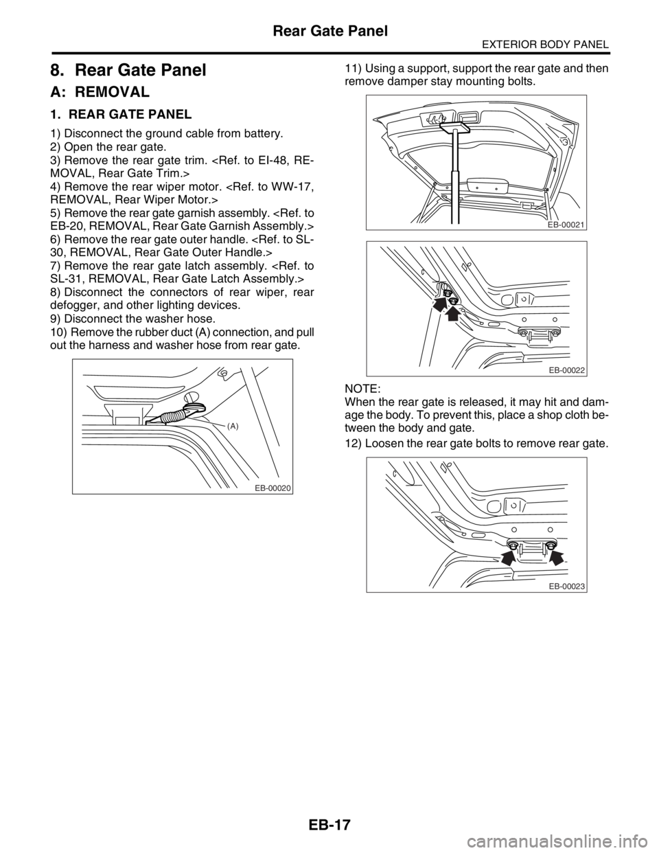
1. REAR GATE PANEL
1) Disconnect the ground cable from battery.
2) Open the rear gate.
3) Remove the rear gate trim.
MOVAL, Rear Gate Trim.>
4) Remove the rear wiper motor.
REMOVAL, Rear Wiper Motor.>
5) Remove the rear gate garnish assembly.
EB-20, REMOVAL, Rear Gate Garnish Assembly.>
6) Remove the rear gate outer handle.
30, REMOVAL, Rear Gate Outer Handle.>
7) Remove the rear gate latch assembly.
SL-31, REMOVAL, Rear Gate Latch Assembly.>
8) Disconnect the connectors of rear wiper, rear
defogger, and other lighting devices.
9) Disconnect the washer hose.
10) Remove the rubber duct (A) connection, and pull
out the harness and washer hose from rear gate.11) Using a support, support the rear gate and then
remove damper stay mounting bolts.
NOTE:
When the rear gate is released, it may hit and dam-
age the body. To prevent this, place a shop cloth be-
tween the body and gate.
12) Loosen the rear gate bolts to remove rear gate.
(A)
EB-00020
EB-00021
EB-00022
EB-00023
Page 549 of 2870
EB-19
EXTERIOR BODY PANEL
Rear Gate Panel
C: DISPOSAL
1. REAR GATE DAMPER STAY
CAUTION:
Gas is colorless, odorless and harmless. How-
ever, gas pressure may spray cutting powder or
oil. Be sure to wear dust-resistant goggles.
1) Cover with a vinyl case as shown in the figure.
NOTE:
Prevent the vinyl case from being caught by drill
cutting edge.
2) Lift the body-side slightly with piston rods fully
extended, and secure the body side on vise stand.
Drill a hole in 2 to 3 mm (0.08 to 0.12 in) diameter at
a point 10 to 200 mm (0.39 to 7.87 in) from the door
side, and bleed the rear gate damper stay com-
pletely.
(1) Rear gate damper stay
(2) Vinyl sack
(1) Body-side
(2) Door-side
(3) 190 mm (7.48 in)
(4) 10 mm (0.39 in)
(5) Piston rod
(6) Cylinder
(7) Portion to be drilled
(1)
(2)
EB-00031
(3) (4)
(1)
(5)
(6)(7)(2)
EB-00032