Page 289 of 2870

WIPER AND WASHER SYSTEM
WW
Page
1. General Description ....................................................................................2
2. Wiper and Washer System .........................................................................6
3. Combination Switch (Wiper)........................................................................7
4. Wiper Blade.................................................................................................9
5. Washer Tank and Motor............................................................................11
6. Front Wiper Arm ........................................................................................12
7. Front Wiper Motor and Link.......................................................................13
8. Front Washer Nozzle ................................................................................15
9. Rear Wiper Arm ........................................................................................16
10. Rear Wiper Motor ......................................................................................17
11. Rear Washer .............................................................................................18
12. Wiper Control Relay ..................................................................................19
13. Headlight Washer......................................................................................20
Page 292 of 2870
WW-4
WIPER AND WASHER SYSTEM
General Description
3. WASHER TANK
(1) Washer nozzle (7) Grommet (13) Valve
(2) Washer hose (8) Headlight washer motor
(3) Washer tank (9) Motor bracketTightening torque: N·m (kgf-m, ft-lb)
(4) Washer tank cap (10) Headlight washer caseT: 6.0 (0.61, 4.4)
(5) Front washer motor (11) Headlight washer upper nozzle
(6) Rear washer motor (12) Headlight washer lower nozzle
WW-00097
(1) (1)
(1)(2)
(2) (10)
(11)
(12)
(13)
(2)
(2)(8)
(7)
(6) (5)(9)
T
(3)
(4)
Page 299 of 2870

WW-11
WIPER AND WASHER SYSTEM
Washer Tank and Motor
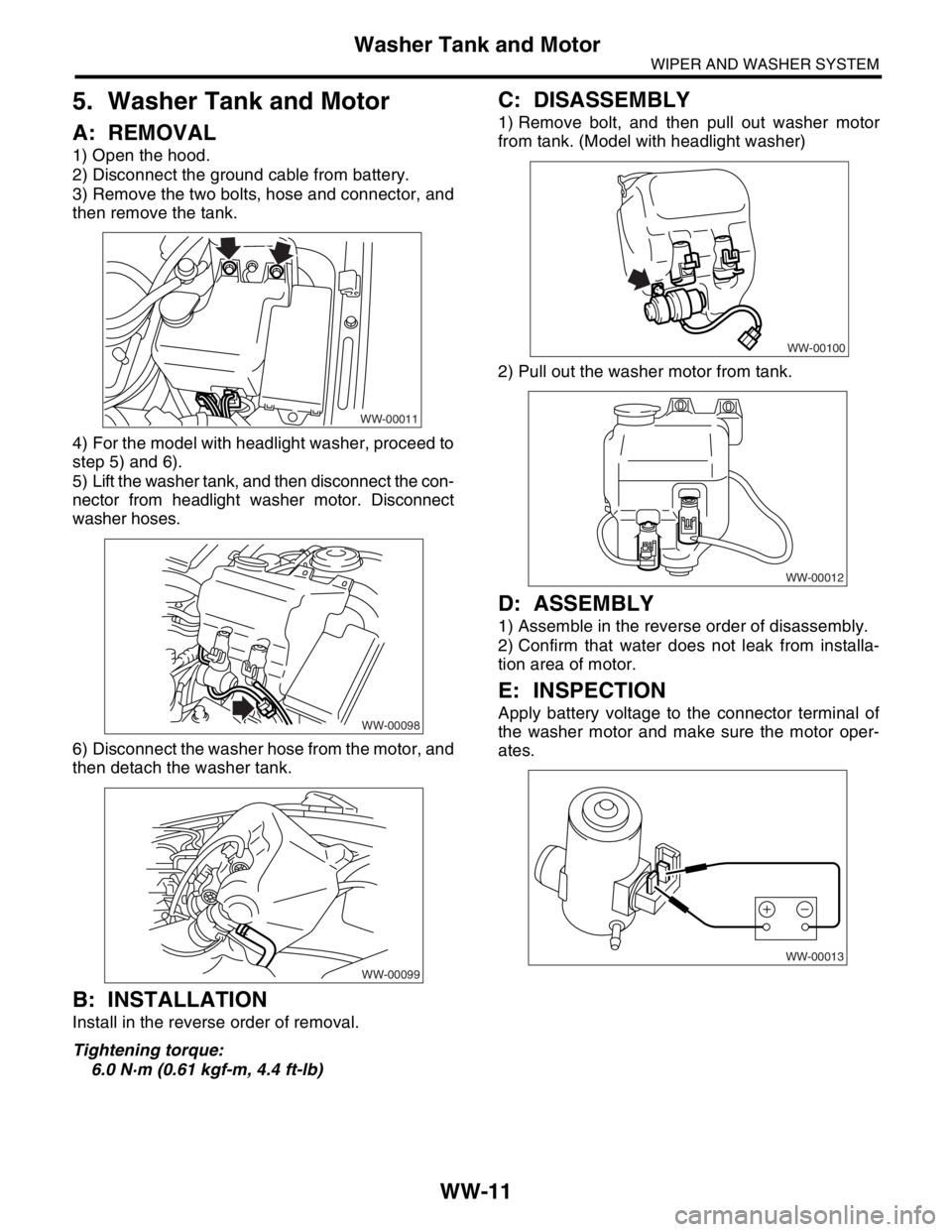
5. Washer Tank and Motor
A: REMOVAL
1) Open the hood.
2) Disconnect the ground cable from battery.
3) Remove the two bolts, hose and connector, and
then remove the tank.
4) For the model with headlight washer, proceed to
step 5) and 6).
5) Lift the washer tank, and then disconnect the con-
nector from headlight washer motor. Disconnect
washer hoses.
6) Disconnect the washer hose from the motor, and
then detach the washer tank.
B: INSTALLATION
Install in the reverse order of removal.
Tightening torque:
6.0 N·m (0.61 kgf-m, 4.4 ft-lb)
C: DISASSEMBLY
1) Remove bolt, and then pull out washer motor
from tank. (Model with headlight washer)
2) Pull out the washer motor from tank.
D: ASSEMBLY
1) Assemble in the reverse order of disassembly.
2) Confirm that water does not leak from installa-
tion area of motor.
E: INSPECTION
Apply battery voltage to the connector terminal of
the washer motor and make sure the motor oper-
ates.
WW-00011
WW-00098
WW-00099
WW-00100
WW-00012
WW-00013
Page 308 of 2870
WW-20
WIPER AND WASHER SYSTEM
Headlight Washer
13.Headlight Washer
A: REMOVAL
1) Disconnect the ground cable from the battery.
2) Remove the front grille.
AL, Front Grille.>
3) Remove the headlight.
AL, Headlight Assembly.>
4) Draw out headlight washer hose.
5) Disconnect hose (A) from valve (B).
NOTE:
Washer fluid may drain from valve. Put a pan under
the valve, then disconnect valve from hose while
pinching the hose edge.
6) Remove nozzle cover (A).
7) Push the three pawls to remove outer nozzle (A).
Then pull out inner nozzle (B).
NOTE:
Before pushing the outer nozzle pawls, cover the
bumper to avoid scratches.
B: INSTALLATION
Install in the reverse order of removal.
WW-00102
(B) (A)
(A)
WW-00109
(A)
WW-00110
(A)
(B)
Page 309 of 2870

FUJI HEAVY INDUSTRIES LTD. G8080GE7
2004 FORESTER SERVICE MANUAL QUICK REFERENCE INDEX
BODY SECTION
This service manual has been prepared
to provide SUBARU service personnel
with the necessary information and data
for the correct maintenance and repair
of SUBARU vehicles.
This manual includes the procedures
for maintenance, disassembling, reas-
sembling, inspection and adjustment of
components and diagnostics for guid-
ance of experienced mechanics.
Please peruse and utilize this manual
fully to ensure complete repair work for
satisfying our customers by keeping
their vehicle in optimum condition.
When replacement of parts during
repair work is needed, be sure to use
SUBARU genuine parts.
All information, illustration and specifi-
cations contained in this manual are
based on the latest product information
available at the time of publication
approval.HVAC SYSTEM
(HEATER, VENTILATOR AND A/C)AC
HVAC SYSTEM (AUTO A/C)
(DIAGNOSTIC)AC
AIRBAG SYSTEM AB
AIRBAG SYSTEM (DIAGNOSTIC) AB
SEAT BELT SYSTEM SB
LIGHTING SYSTEM LI
WIPER AND WASHER SYSTEM WW
ENTERTAINMENT ET
COMMUNICATION SYSTEM COM
GLASS/WINDOW/MIRROR GW
BODY STRUCTURE BS
INSTRUMENTATION/DRIVER INFO IDI
SEAT SE
SECURITY AND LOCK SL
SUNROOF/T-TOP/CONVERTIBLE TOP
(SUNROOF)SR
EXTERIOR/INTERIOR TRIM EI
EXTERIOR BODY PANEL EB
Page 315 of 2870

ET-5
ENTERTAINMENT
Radio Body
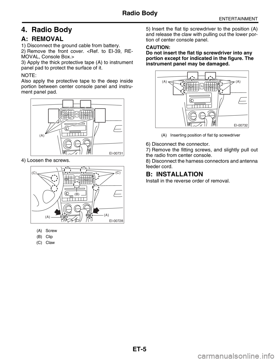
4. Radio Body
A: REMOVAL
1) Disconnect the ground cable from battery.
2) Remove the front cover.
MOVAL, Console Box.>
3) Apply the thick protective tape (A) to instrument
panel pad to protect the surface of it.
NOTE:
Also apply the protective tape to the deep inside
portion between center console panel and instru-
ment panel pad.
4) Loosen the screws.5) Insert the flat tip screwdriver to the position (A)
and release the claw with pulling out the lower por-
tion of center console panel.
CAUTION:
Do not insert the flat tip screwdriver into any
portion except for indicated in the figure. The
instrument panel may be damaged.
6) Disconnect the connector.
7) Remove the fitting screws, and slightly pull out
the radio from center console.
8) Disconnect the harness connectors and antenna
feeder cord.
B: INSTALLATION
Install in the reverse order of removal.
(A) Screw
(B) Clip
(C) Claw
EI-00731
(A)
EI-00728
(C)
(A)(A)(C)
(B)
(A) Inserting position of flat tip screwdriver
EI-00732
(A) (A)
Page 321 of 2870

FUJI HEAVY INDUSTRIES LTD. G8080GE7
2004 FORESTER SERVICE MANUAL QUICK REFERENCE INDEX
BODY SECTION
This service manual has been prepared
to provide SUBARU service personnel
with the necessary information and data
for the correct maintenance and repair
of SUBARU vehicles.
This manual includes the procedures
for maintenance, disassembling, reas-
sembling, inspection and adjustment of
components and diagnostics for guid-
ance of experienced mechanics.
Please peruse and utilize this manual
fully to ensure complete repair work for
satisfying our customers by keeping
their vehicle in optimum condition.
When replacement of parts during
repair work is needed, be sure to use
SUBARU genuine parts.
All information, illustration and specifi-
cations contained in this manual are
based on the latest product information
available at the time of publication
approval.HVAC SYSTEM
(HEATER, VENTILATOR AND A/C)AC
HVAC SYSTEM (AUTO A/C)
(DIAGNOSTIC)AC
AIRBAG SYSTEM AB
AIRBAG SYSTEM (DIAGNOSTIC) AB
SEAT BELT SYSTEM SB
LIGHTING SYSTEM LI
WIPER AND WASHER SYSTEM WW
ENTERTAINMENT ET
COMMUNICATION SYSTEM COM
GLASS/WINDOW/MIRROR GW
BODY STRUCTURE BS
INSTRUMENTATION/DRIVER INFO IDI
SEAT SE
SECURITY AND LOCK SL
SUNROOF/T-TOP/CONVERTIBLE TOP
(SUNROOF)SR
EXTERIOR/INTERIOR TRIM EI
EXTERIOR BODY PANEL EB
Page 326 of 2870
COM-4
COMMUNICATION SYSTEM
Horn
3. Horn
A: REMOVAL
1) Disconnect the ground cable from battery.
2) Remove the front fog light assembly (LH).
to LI-19, REMOVAL, Front Fog Light Assembly.>
3) Remove the horn bracket mounting bolt (A).
4) Disconnect the harness connector and remove
the horn assembly (B).
B: INSTALLATION
Install in the reverse order of removal.
C: INSPECTION
With 12 V direct current supplied between horn ter-
minal and case ground, check that the horn sounds
properly.
COM00002
(B)(A)
COM00003