2004 SUBARU FORESTER light
[x] Cancel search: lightPage 2816 of 2870
5MT-103
MANUAL TRANSMISSION AND DIFFERENTIAL
Speedometer Gear
22.Speedometer Gear
A: REMOVAL
1) Remove the manual transmission assembly
from vehicle.
2) Remove the back-up light switch and neutral po-
sition switch.
3) Remove the transfer case with extension case
assembly.
4) Remove the transmission case.
5) Remove the vehicle speed sensor.
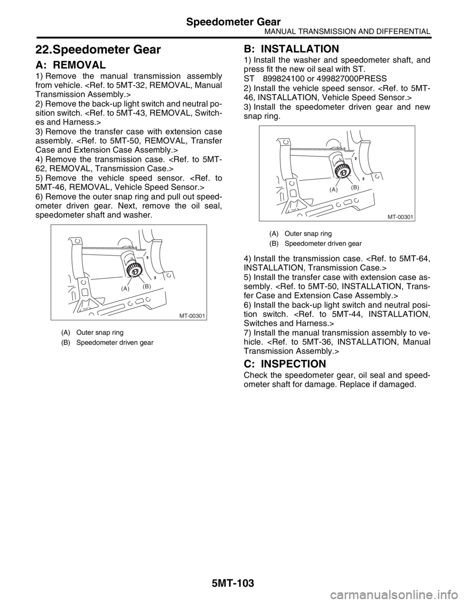
6) Remove the outer snap ring and pull out speed-
ometer driven gear. Next, remove the oil seal,
speedometer shaft and washer.
B: INSTALLATION
1) Install the washer and speedometer shaft, and
press fit the new oil seal with ST.
ST 899824100 or 499827000PRESS
2) Install the vehicle speed sensor.
3) Install the speedometer driven gear and new
snap ring.
4) Install the transmission case.
5) Install the transfer case with extension case as-
sembly.
6) Install the back-up light switch and neutral posi-
tion switch.
7) Install the manual transmission assembly to ve-
hicle.
C: INSPECTION
Check the speedometer gear, oil seal and speed-
ometer shaft for damage. Replace if damaged.
(A) Outer snap ring
(B) Speedometer driven gear
MT-00301
(A)(B)
(A) Outer snap ring
(B) Speedometer driven gear
MT-00301
(A)(B)
Page 2817 of 2870
5MT-104
MANUAL TRANSMISSION AND DIFFERENTIAL
Reverse Idler Gear
23.Reverse Idler Gear
A: REMOVAL
1) Remove the manual transmission assembly
from vehicle.
2) Remove the back-up light switch and neutral po-
sition switch.
3) Remove the transfer case with extension case
assembly.
4) Remove the transmission case.
5) Remove the drive pinion shaft assembly.
bly.>
6) Remove the main shaft assembly.
Single-Range model
Dual-Range model
7) Remove the differential assembly.
8) Remove the shifter forks and rods.
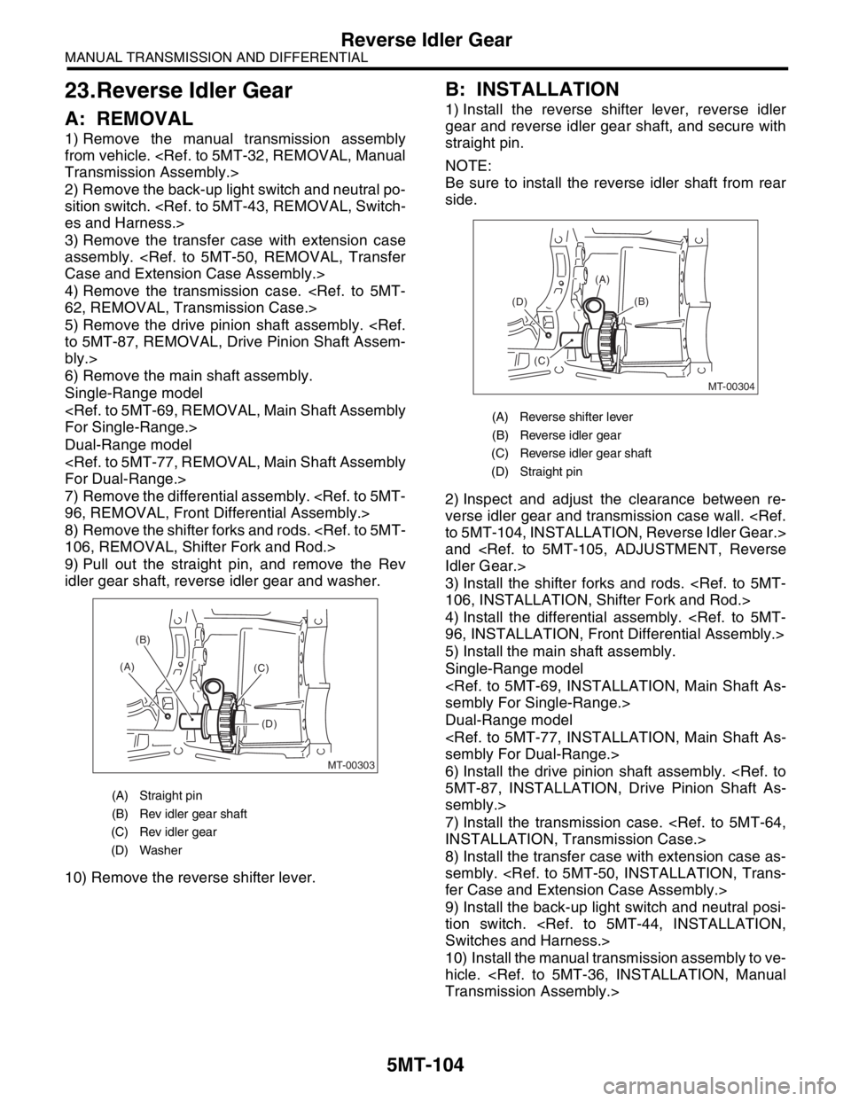
9) Pull out the straight pin, and remove the Rev
idler gear shaft, reverse idler gear and washer.
10) Remove the reverse shifter lever.
B: INSTALLATION
1) Install the reverse shifter lever, reverse idler
gear and reverse idler gear shaft, and secure with
straight pin.
NOTE:
Be sure to install the reverse idler shaft from rear
side.
2) Inspect and adjust the clearance between re-
verse idler gear and transmission case wall.
and
3) Install the shifter forks and rods.
4) Install the differential assembly.
5) Install the main shaft assembly.
Single-Range model
Dual-Range model
6) Install the drive pinion shaft assembly.
sembly.>
7) Install the transmission case.
8) Install the transfer case with extension case as-
sembly.
9) Install the back-up light switch and neutral posi-
tion switch.
10) Install the manual transmission assembly to ve-
hicle.
(A) Straight pin
(B) Rev idler gear shaft
(C) Rev idler gear
(D) Washer
MT-00303
(A)(B)
(C)
(D)
(A) Reverse shifter lever
(B) Reverse idler gear
(C) Reverse idler gear shaft
(D) Straight pin
MT-00304
(A)
(B)
(D)
(C)
Page 2819 of 2870
5MT-106
MANUAL TRANSMISSION AND DIFFERENTIAL
Shifter Fork and Rod
24.Shifter Fork and Rod
A: REMOVAL
1) Remove the manual transmission assembly
from vehicle.
2) Remove the back-up light switch and neutral po-
sition switch.
3) Remove the transfer case with extension case
assembly.
4) Remove the transmission case.
5) Remove the drive pinion shaft assembly.
bly.>
6) Remove the main shaft assembly.
Single-Range model
Dual-Range model
7) Remove the differential assembly.
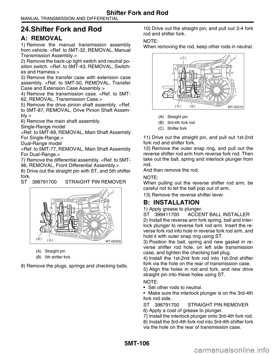
8) Drive out the straight pin with ST, and 5th shifter
fork.
ST 398791700 STRAIGHT PIN REMOVER
9) Remove the plugs, springs and checking balls.10) Drive out the straight pin, and pull out 3-4 fork
rod and shifter fork.
NOTE:
When removing the rod, keep other rods in neutral.
11) Drive out the straight pin, and pull out 1st-2nd
fork rod and shifter fork.
12) Remove the outer snap ring, and pull out the
reverse shifter rod arm from reverse fork rod. Then
take out the ball, spring and interlock plunger from
rod.
And then remove the rod.
NOTE:
When pulling out the reverse shifter rod arm, be
careful not to let the ball pop out of arm.
13) Remove the reverse shifter lever.
B: INSTALLATION
1) Apply grease to plunger.
ST 399411700 ACCENT BALL INSTALLER
2) Install the reverse arm fork spring, ball and inter-
lock plunger to reverse fork rod arm. Insert the re-
verse fork rod into hole in reverse fork rod arm, and
hold it with outer snap ring using ST.
3) Position the ball, spring and new gasket in re-
verse shifter rod hole, on left side transmission
case, and tighten the checking ball plug.
4) Install the 1st-2nd fork rod into 1st-2nd shifter
fork via the hole on the rear of transmission case.
5) Align the holes in rod and fork, and new drive
straight pin into these holes using ST.
NOTE:
Set other rods to neutral.
Make sure the interlock plunger is on the 3rd-4th
fork rod side.
ST 398791700 STRAIGHT PIN REMOVER
6) Apply a coat of grease to plunger.
7) Install the interlock plunger onto 3rd-4th fork rod.
8) Install the 3rd-4th fork rod into 3rd-4th shifter fork
via the hole on the rear of transmission case.
(A) Straight pin
(B) 5th shifter fork
MT-00309(A) (B)
(A) Straight pin
(B) 3rd-4th fork rod
(C) Shifter fork
MT-00310(A)
(B) (C)
Page 2820 of 2870
5MT-107
MANUAL TRANSMISSION AND DIFFERENTIAL
Shifter Fork and Rod
9) Align the holes in rod and fork, and new drive
straight pin into these holes.
NOTE:
Set the reverse fork rod to neutral.
Make sure the interlock plunger (installing be-
fore) is on the reverse fork rod side.
ST 398791700 STRAIGHT PIN REMOVER
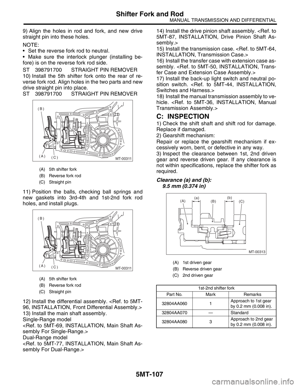
10) Install the 5th shifter fork onto the rear of re-
verse fork rod. Align holes in the two parts and new
drive straight pin into place.
ST 398791700 STRAIGHT PIN REMOVER
11) Position the balls, checking ball springs and
new gaskets into 3rd-4th and 1st-2nd fork rod
holes, and install plugs.
12) Install the differential assembly.
13) Install the main shaft assembly.
Single-Range model
Dual-Range model
sembly.>
15) Install the transmission case.
16) Install the transfer case with extension case as-
sembly.
17) Install the back-up light switch and neutral po-
sition switch.
18) Install the manual transmission assembly to ve-
hicle.
C: INSPECTION
1) Check the shift shaft and shift rod for damage.
Replace if damaged.
2) Gearshift mechanism:
Repair or replace the gearshift mechanism if ex-
cessively worn, bent, or defective in any way.
3) Inspect the clearance between 1st, 2nd driven
gear and reverse driven gear. If any clearance is
not within specifications, replace the shifter fork as
required.
Clearance (a) and (b):
9.5 mm (0.374 in)
(A) 5th shifter fork
(B) Reverse fork rod
(C) Straight pin
(A) 5th shifter fork
(B) Reverse fork rod
(C) Straight pin
MT-00311(C) (A) (B)
MT-00311(C) (A) (B)(A) 1st driven gear
(B) Reverse driven gear
(C) 2nd driven gear
1st-2nd shifter fork
Part No. Mark Remarks
32804AA060 1Approach to 1st gear
by 0.2 mm (0.008 in).
32804AA070 — Standard
32804AA080 3Approach to 2nd gear
by 0.2 mm (0.008 in).
MT-00313
(A)
(B)
(C) (a)(b)
Page 2838 of 2870
CL-12
CLUTCH SYSTEM
General Description
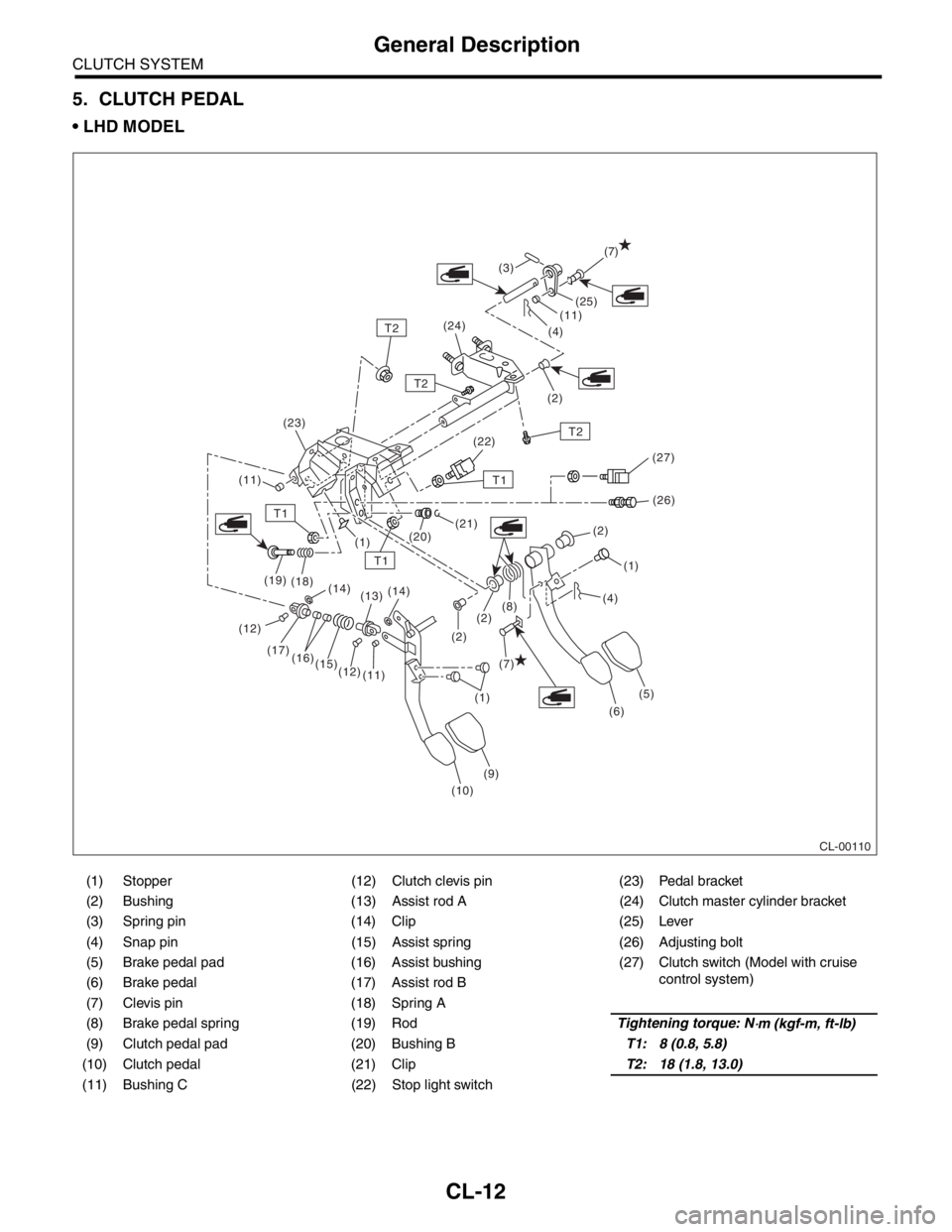
5. CLUTCH PEDAL
LHD MODEL
(1) Stopper (12) Clutch clevis pin (23) Pedal bracket
(2) Bushing (13) Assist rod A (24) Clutch master cylinder bracket
(3) Spring pin (14) Clip (25) Lever
(4) Snap pin (15) Assist spring (26) Adjusting bolt
(5) Brake pedal pad (16) Assist bushing (27) Clutch switch (Model with cruise
control system)
(6) Brake pedal (17) Assist rod B
(7) Clevis pin (18) Spring A
(8) Brake pedal spring (19) RodTightening torque: N
⋅m (kgf-m, ft-lb)
(9) Clutch pedal pad (20) Bushing BT1: 8 (0.8, 5.8)
(10) Clutch pedal (21) ClipT2: 18 (1.8, 13.0)
(11) Bushing C (22) Stop light switch
CL-00110
(7)
(7) (12)
T1
T1
T1
T2
T2
T2(25)
(11)
(11)(4)
(2) (3)
(24)
(22)
(26)
(21)
(20)
(1)
(1)(1) (2)
(2)
(6)
(9)
(10) (11) (12) (15) (16) (17) (19)
(18)
(14)
(13)(14)
(5) (2)(8)(4) (23)
(27)
Page 2847 of 2870
CL-21
CLUTCH SYSTEM
Release Bearing and Lever
B: INSTALLATION
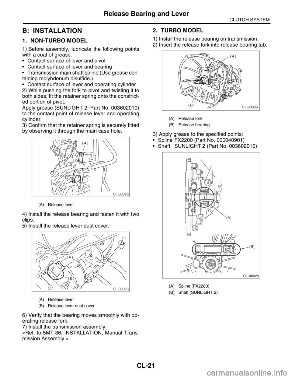
1. NON-TURBO MODEL
1) Before assembly, lubricate the following points
with a coat of grease.
Contact surface of lever and pivot
Contact surface of lever and bearing
Transmission main shaft spline (Use grease con-
taining molybdenum disulfide.)
Contact surface of lever and operating cylinder
2) While pushing the fork to pivot and twisting it to
both sides, fit the retainer spring onto the constrict-
ed portion of pivot.
Apply grease (SUNLIGHT 2: Part No. 003602010)
to the contact point of release lever and operating
cylinder.
3) Confirm that the retainer spring is securely fitted
by observing it through the main case hole.
4) Install the release bearing and fasten it with two
clips.
5) Install the release lever dust cover.
6) Verify that the bearing moves smoothly with op-
erating release fork.
7) Install the transmission assembly.
2. TURBO MODEL
1) Install the release bearing on transmission.
2) Insert the release fork into release bearing tab.
3) Apply grease to the specified points:
Spline FX2200 (Part No. 000040901)
Shaft SUNLIGHT 2 (Part No. 003602010)
(A) Release lever
(A) Release lever
(B) Release lever dust cover
CL-00026
(A)
CL-00023
(A)
(B)
(A) Release fork
(B) Release bearing
(A) Spline (FX2200)
(B) Shaft (SUNLIGHT 2)
CL-00028
(A)
(B)
CL-00029 (A)
(B)
Page 2851 of 2870
CL-25
CLUTCH SYSTEM
Operating Cylinder
B: INSTALLATION
1) Apply grease (SUNLIGHT 2: Part No.
003602010) to the contact point of the release lever
and operating cylinder.
2) Install in the reverse order of removal.
Before installing the operating cylinder, apply
grease (SUNLIGHT 2: Part No. 003602010) to con-
tact point of the release lever and operating cylin-
der.
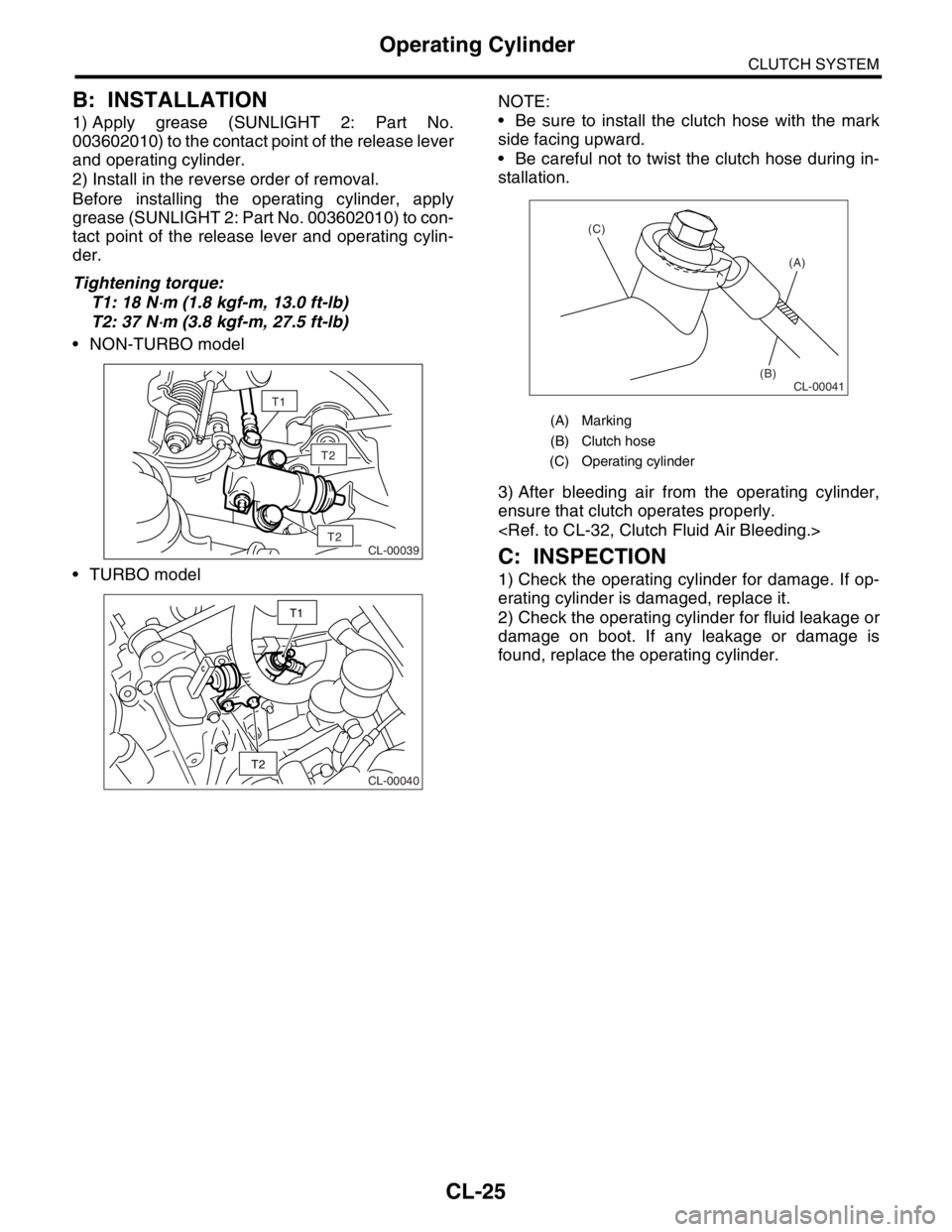
Tightening torque:
T1: 18 N
⋅m (1.8 kgf-m, 13.0 ft-lb)
T2: 37 N
⋅m (3.8 kgf-m, 27.5 ft-lb)
NON-TURBO model
TURBO modelNOTE:
Be sure to install the clutch hose with the mark
side facing upward.
Be careful not to twist the clutch hose during in-
stallation.
3) After bleeding air from the operating cylinder,
ensure that clutch operates properly.
C: INSPECTION
1) Check the operating cylinder for damage. If op-
erating cylinder is damaged, replace it.
2) Check the operating cylinder for fluid leakage or
damage on boot. If any leakage or damage is
found, replace the operating cylinder.
T2
CL-00039T2
T1
CL-00040
T2
T1
(A) Marking
(B) Clutch hose
(C) Operating cylinder
CL-00041
(A)
(B) (C)
Page 2860 of 2870
CL-34
CLUTCH SYSTEM
Clutch Pedal
10.Clutch Pedal
A: REMOVAL
1. LHD MODEL
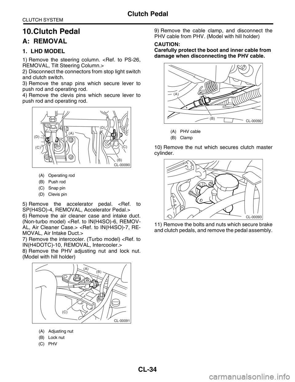
1) Remove the steering column.
2) Disconnect the connectors from stop light switch
and clutch switch.
3) Remove the snap pins which secure lever to
push rod and operating rod.
4) Remove the clevis pins which secure lever to
push rod and operating rod.
5) Remove the accelerator pedal.
6) Remove the air cleaner case and intake duct.
(Non-turbo model)
7) Remove the intercooler. (Turbo model)
8) Remove the PHV adjusting nut and lock nut.
(Model with hill holder)9) Remove the cable clamp, and disconnect the
PHV cable from PHV. (Model with hill holder)
CAUTION:
Carefully protect the boot and inner cable from
damage when disconnecting the PHV cable.
10) Remove the nut which secures clutch master
cylinder.
11) Remove the bolts and nuts which secure brake
and clutch pedals, and remove the pedal assembly.
(A) Operating rod
(B) Push rod
(C) Snap pin
(D) Clevis pin
(A) Adjusting nut
(B) Lock nut
(C) PHV
(D)
(B)(C)
(C) (D)(A)
CL-00090
CL-00091
(C)(B) (A)
(A) PHV cable
(B) Clamp
(B) (A)
CL-00092
CL-00093