Page 2754 of 2870
5MT-42
MANUAL TRANSMISSION AND DIFFERENTIAL
Differential Side Retainer Oil Seal
6. Differential Side Retainer Oil
Seal
A: INSPECTION
Check the differential side retainer oil seal for leak-
age of gear oil. If oil leaks, replace the oil seal.
B: REPLACEMENT
1) Lift-up the vehicle.
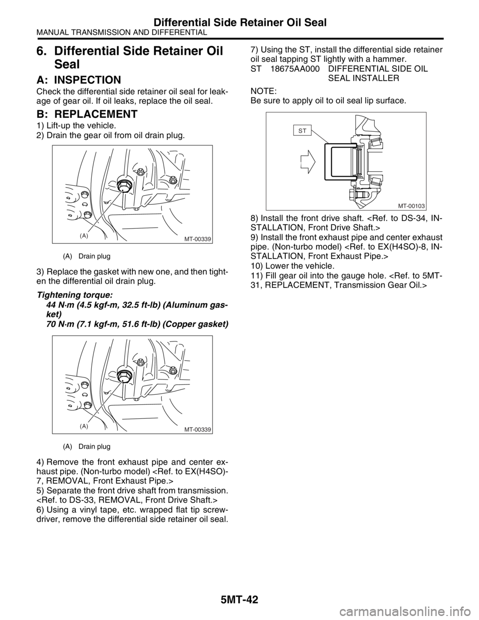
2) Drain the gear oil from oil drain plug.
3) Replace the gasket with new one, and then tight-
en the differential oil drain plug.
Tightening torque:
44 N·m (4.5 kgf-m, 32.5 ft-lb) (Aluminum gas-
ket)
70 N·m (7.1 kgf-m, 51.6 ft-lb) (Copper gasket)
4) Remove the front exhaust pipe and center ex-
haust pipe. (Non-turbo model)
7, REMOVAL, Front Exhaust Pipe.>
5) Separate the front drive shaft from transmission.
6) Using a vinyl tape, etc. wrapped flat tip screw-
driver, remove the differential side retainer oil seal.7) Using the ST, install the differential side retainer
oil seal tapping ST lightly with a hammer.
ST 18675AA000 DIFFERENTIAL SIDE OIL
SEAL INSTALLER
NOTE:
Be sure to apply oil to oil seal lip surface.
8) Install the front drive shaft.
STALLATION, Front Drive Shaft.>
9) Install the front exhaust pipe and center exhaust
pipe. (Non-turbo model)
STALLATION, Front Exhaust Pipe.>
10) Lower the vehicle.
11) Fill gear oil into the gauge hole.
31, REPLACEMENT, Transmission Gear Oil.>
(A) Drain plug
(A) Drain plug
(A)
MT-00339
(A)
MT-00339
MT-00103
ST
Page 2755 of 2870
5MT-43
MANUAL TRANSMISSION AND DIFFERENTIAL
Switches and Harness
7. Switches and Harness
A: REMOVAL
1. BACK-UP LIGHT AND NEUTRAL POSI-
TION SWITCH
1) Disconnect the ground cable from battery.
2) Remove the air intake duct and cleaner case.
Case.>
3) Remove the intercooler (Turbo model).
IN(H4DOTC)-10, REMOVAL, Intercooler.>
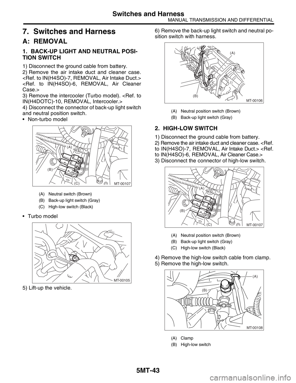
4) Disconnect the connector of back-up light switch
and neutral position switch.
Non-turbo model
Turbo model
5) Lift-up the vehicle.6) Remove the back-up light switch and neutral po-
sition switch with harness.
2. HIGH-LOW SWITCH
1) Disconnect the ground cable from battery.
2) Remove the air intake duct and cleaner case.
to IN(H4SO)-7, REMOVAL, Air Intake Duct.>
to IN(H4SO)-6, REMOVAL, Air Cleaner Case.>
3) Disconnect the connector of high-low switch.
4) Remove the high-low switch cable from clamp.
5) Remove the high-low switch.
(A) Neutral switch (Brown)
(B) Back-up light switch (Gray)
(C) High-low switch (Black)
MT-00107
(B)
(C)
(A)
MT-00105
(A) Neutral position switch (Brown)
(B) Back-up light switch (Gray)
(A) Neutral position switch (Brown)
(B) Back-up light switch (Gray)
(C) High-low switch (Black)
(A) Clamp
(B) High-low switch
MT-00106
(A)
(B)
MT-00107
(B)
(C)
(A)
MT-00108
(B)(A)
Page 2756 of 2870
5MT-44
MANUAL TRANSMISSION AND DIFFERENTIAL
Switches and Harness
B: INSTALLATION
1. BACK-UP LIGHT SWITCH AND NEU-
TRAL POSITION SWITCH
1) Install the back-up light switch and neutral posi-
tion switch with harness.
Tightening torque:
24.5 N·m (2.5 kgf-m, 18.1 ft-lb)
2) Connect the connector of back-up light switch
and neutral position switch.
3) Install the air intake duct and cleaner case.
to IN(H4SO)-7, INSTALLATION, Air Intake Duct.>
Case.>
4) Install the intercooler. (Turbo model)
cooler.>
5) Connect the battery ground cable to battery.
2. HIGH-LOW SWITCH
1) Install the high-low switch.
Tightening torque:
25 N·m (2.5 kgf-m, 18.1 ft-lb)
2) Install the high-low switch cable to clamp.
3) Connect the connector of high-low switch.
4) Install the air intake duct and cleaner case.
to IN(H4SO)-7, INSTALLATION, Air Intake Duct.>
Case.>
5) Connect the battery ground cable to battery.
(A) Neutral position switch (Brown)
(B) Back-up light switch (Gray)
MT-00106
(A)
(B)
Page 2757 of 2870
5MT-45
MANUAL TRANSMISSION AND DIFFERENTIAL
Switches and Harness
C: INSPECTION
1. BACK-UP LIGHT SWITCH
Inspect the back-up light switch.
SPECTION, Back-up Light System.>
2. NEUTRAL POSITION SWITCH
1) Turn the ignition switch to OFF.
2) Disconnect the connector of neutral position
switch.
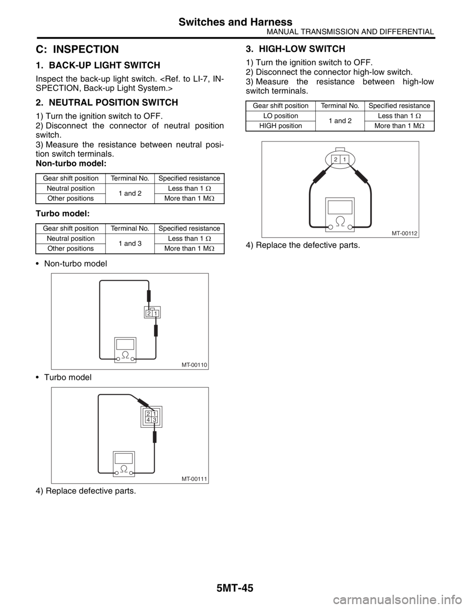
3) Measure the resistance between neutral posi-
tion switch terminals.
Non-turbo model:
Turbo model:
Non-turbo model
Turbo model
4) Replace defective parts.
3. HIGH-LOW SWITCH
1) Turn the ignition switch to OFF.
2) Disconnect the connector high-low switch.
3) Measure the resistance between high-low
switch terminals.
4) Replace the defective parts.
Gear shift position Terminal No. Specified resistance
Neutral position
1 and 2Less than 1 Ω
Other positions More than 1 MΩ
Gear shift position Terminal No. Specified resistance
Neutral position
1 and 3Less than 1 Ω
Other positions More than 1 MΩ
MT-00110
1 2
MT-00111
1 2
3 4
Gear shift position Terminal No. Specified resistance
LO position
1 and 2Less than 1 Ω
HIGH position More than 1 MΩ
MT-00112
1 2
Page 2762 of 2870
5MT-50
MANUAL TRANSMISSION AND DIFFERENTIAL
Transfer Case and Extension Case Assembly
11.Transfer Case and Extension
Case Assembly
A: REMOVAL
1) Remove the manual transmission assembly
from vehicle.
Transmission Assembly.>
2) Remove the back-up light switch and neutral po-
sition switch.
es and Harness.>
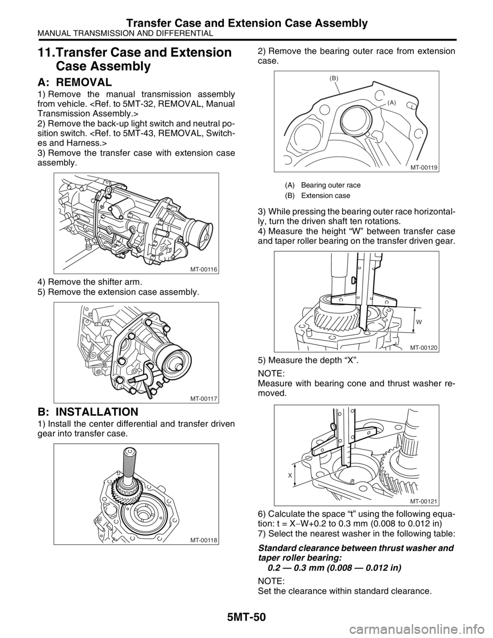
3) Remove the transfer case with extension case
assembly.
4) Remove the shifter arm.
5) Remove the extension case assembly.
B: INSTALLATION
1) Install the center differential and transfer driven
gear into transfer case.2) Remove the bearing outer race from extension
case.
3) While pressing the bearing outer race horizontal-
ly, turn the driven shaft ten rotations.
4) Measure the height “W” between transfer case
and taper roller bearing on the transfer driven gear.
5) Measure the depth “X”.
NOTE:
Measure with bearing cone and thrust washer re-
moved.
6) Calculate the space “t” using the following equa-
tion: t = X−W+0.2 to 0.3 mm (0.008 to 0.012 in)
7) Select the nearest washer in the following table:
Standard clearance between thrust washer and
taper roller bearing:
0.2 — 0.3 mm (0.008 — 0.012 in)
NOTE:
Set the clearance within standard clearance.
MT-00116
MT-00117
MT-00118
(A) Bearing outer race
(B) Extension case
MT-00119
(B)
(A)
MT-00120
W
MT-00121
X
Page 2766 of 2870
5MT-54
MANUAL TRANSMISSION AND DIFFERENTIAL
Transfer Drive Gear
12.Transfer Drive Gear
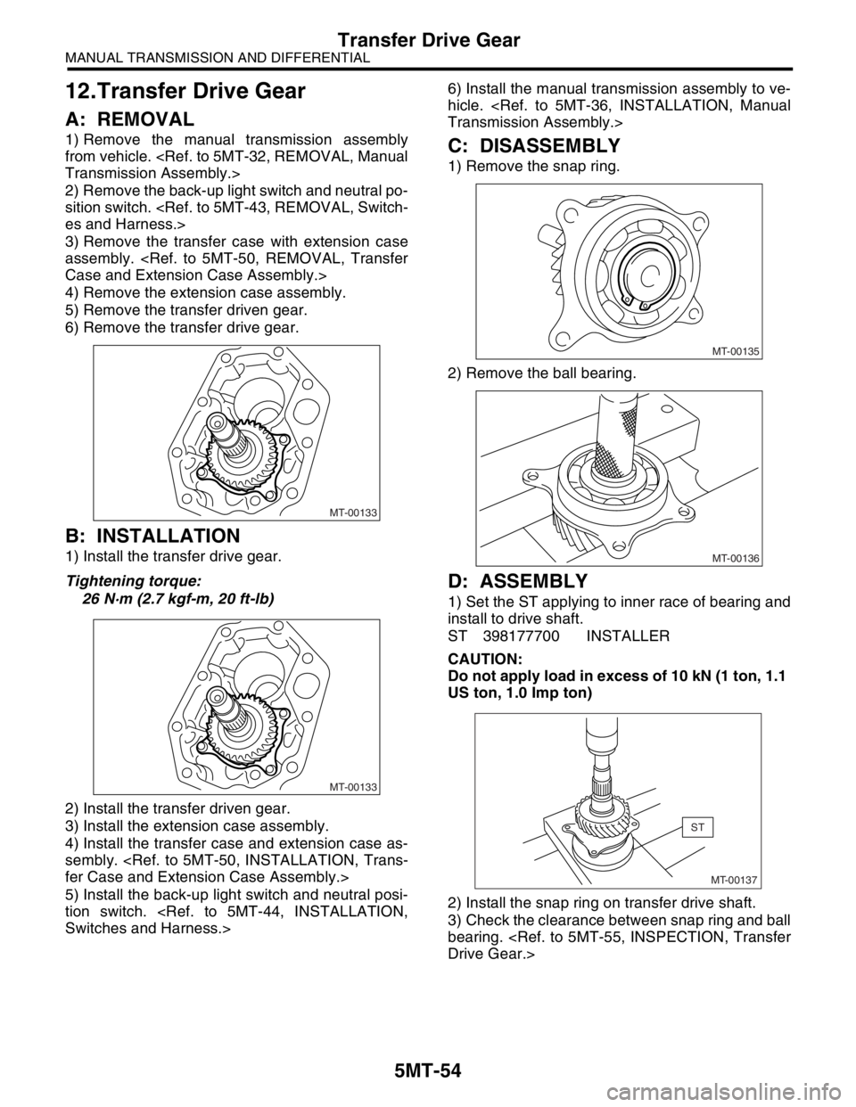
A: REMOVAL
1) Remove the manual transmission assembly
from vehicle.
Transmission Assembly.>
2) Remove the back-up light switch and neutral po-
sition switch.
es and Harness.>
3) Remove the transfer case with extension case
assembly.
Case and Extension Case Assembly.>
4) Remove the extension case assembly.
5) Remove the transfer driven gear.
6) Remove the transfer drive gear.
B: INSTALLATION
1) Install the transfer drive gear.
Tightening torque:
26 N·m (2.7 kgf-m, 20 ft-lb)
2) Install the transfer driven gear.
3) Install the extension case assembly.
4) Install the transfer case and extension case as-
sembly.
fer Case and Extension Case Assembly.>
5) Install the back-up light switch and neutral posi-
tion switch.
Switches and Harness.>6) Install the manual transmission assembly to ve-
hicle.
Transmission Assembly.>
C: DISASSEMBLY
1) Remove the snap ring.
2) Remove the ball bearing.
D: ASSEMBLY
1) Set the ST applying to inner race of bearing and
install to drive shaft.
ST 398177700 INSTALLER
CAUTION:
Do not apply load in excess of 10 kN (1 ton, 1.1
US ton, 1.0 Imp ton)
2) Install the snap ring on transfer drive shaft.
3) Check the clearance between snap ring and ball
bearing.
Drive Gear.>
MT-00133
MT-00133
MT-00135
MT-00136
MT-00137
ST
Page 2769 of 2870
5MT-56
MANUAL TRANSMISSION AND DIFFERENTIAL
Transfer Driven Gear
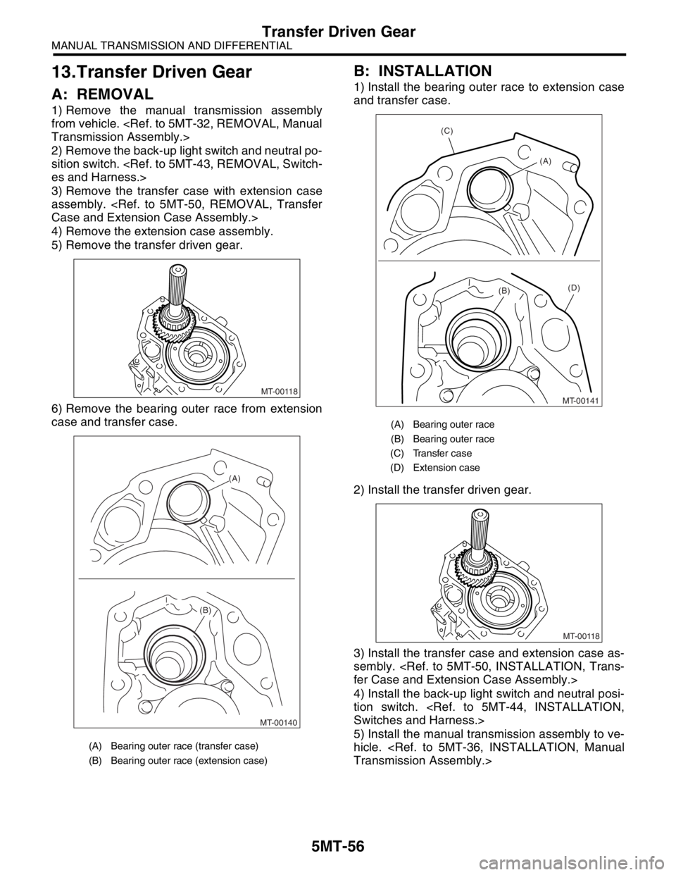
13.Transfer Driven Gear
A: REMOVAL
1) Remove the manual transmission assembly
from vehicle.
Transmission Assembly.>
2) Remove the back-up light switch and neutral po-
sition switch.
es and Harness.>
3) Remove the transfer case with extension case
assembly.
Case and Extension Case Assembly.>
4) Remove the extension case assembly.
5) Remove the transfer driven gear.
6) Remove the bearing outer race from extension
case and transfer case.
B: INSTALLATION
1) Install the bearing outer race to extension case
and transfer case.
2) Install the transfer driven gear.
3) Install the transfer case and extension case as-
sembly.
fer Case and Extension Case Assembly.>
4) Install the back-up light switch and neutral posi-
tion switch.
Switches and Harness.>
5) Install the manual transmission assembly to ve-
hicle.
Transmission Assembly.>
(A) Bearing outer race (transfer case)
(B) Bearing outer race (extension case)
MT-00118
MT-00140 (B)
(A)
(A) Bearing outer race
(B) Bearing outer race
(C) Transfer case
(D) Extension case
(C)
(A)
(D)(B)
MT-00141
MT-00118
Page 2771 of 2870
5MT-58
MANUAL TRANSMISSION AND DIFFERENTIAL
Center Differential
14.Center Differential
A: REMOVAL
1) Remove the manual transmission assembly
from vehicle.
Transmission Assembly.>
2) Remove the transfer case with extension case
assembly.
Case and Extension Case Assembly.>
3) Remove the extension case assembly.
5MT-50, REMOVAL, Transfer Case and Extension
Case Assembly.>
4) Remove the transfer driven gear.
56, REMOVAL, Transfer Driven Gear.>
5) Remove the center differential.
B: INSTALLATION
1) Install the center differential into transfer case.
2) Install the transfer driven gear.
INSTALLATION, Transfer Driven Gear.>
3) Install the extension case assembly.
5MT-50, INSTALLATION, Transfer Case and Ex-
tension Case Assembly.>
4) Install the transfer case with extension case as-
sembly.
fer Case and Extension Case Assembly.>
5) Install the back-up light switch and neutral posi-
tion switch.
Switches and Harness.>
6) Install the manual transmission assembly to ve-
hicle.
Transmission Assembly.>
C: DISASSEMBLY
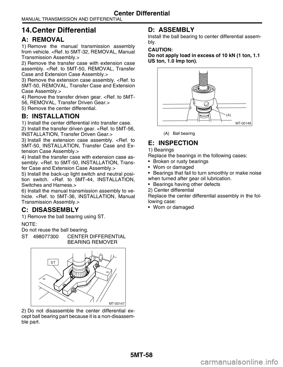
1) Remove the ball bearing using ST.
NOTE:
Do not reuse the ball bearing.
ST 498077300 CENTER DIFFERENTIAL
BEARING REMOVER
2) Do not disassemble the center differential ex-
cept ball bearing part because it is a non-disassem-
ble part.
D: ASSEMBLY
Install the ball bearing to center differential assem-
bly.
CAUTION:
Do not apply load in excess of 10 kN (1 ton, 1.1
US ton, 1.0 Imp ton).
E: INSPECTION
1) Bearings
Replace the bearings in the following cases:
Broken or rusty bearings
Worn or damaged
Bearings that fail to turn smoothly or make noise
when turned after gear oil lubrication.
Bearings having other defects
2) Center differential
Replace the center differential assembly in the fol-
lowing case:
Worn or damaged
MT-00147
ST
(A) Ball bearing
MT-00148 (A)