2004 SUBARU FORESTER light
[x] Cancel search: lightPage 2694 of 2870

4AT(H4DOTC)-118
AUTOMATIC TRANSMISSION (DIAGNOSTIC)
Diagnostic Procedure without Diagnostic Trouble Code (DTC)
2 CHECK POWER SWITCH OPERATION.When the POWER switch is
turned to ON, does LED light
up?Go to step CHECK
HOLD SWITCH.
120, CHECK
HOLD SWITCH,
Diagnostic Proce-
dure without Diag-
nostic Trouble
Code (DTC).>Go to step 3.
3 CHECK POWER INDICATOR LIGHT.
1) Turn the ignition switch to OFF.
2) Remove the combination meter.
3) Remove the POWER indicator light bulb
from combination meter.Is the POWER indicator light
bulb OK?Go to step 4.Replace the
POWER indicator
light bulb.
tion Meter Assem-
bly.>
4 CHECK POWER SWITCH GROUND CIR-
CUIT.
1) Turn the ignition switch to OFF.
2) Disconnect the connector from POWER
switch.
3) Measure the resistance of harness connector
between POWER switch and chassis ground.
Connector & terminal
LHD model
(R92) No. 4 — Chassis ground:
RHD model
(B133) No. 4 — Chassis ground:Is the resistance less than 1
Ω?Go to step 5.Repair the open
circuit in harness
between POWER
switch and chas-
sis ground.
5 CHECK POWER SWITCH.
1) Turn the POWER switch to ON.
2) Measure the resistance between terminals
of POWER switch.
Te r m i n a l s
No. 5 — No. 4:Is the resistance less than 1
Ω?Go to step 6.Replace the
POWER switch.
6 CHECK POWER SWITCH.
1) Turn the POWER switch to OFF.
2) Measure the resistance between terminals
of POWER switch.
Te r m i n a l s
No. 5 — No. 4:Is the resistance more than1
MΩ?Go to step 7.Replace the
POWER switch.
7 CHECK HARNESS CONNECTOR BETWEEN
TCM AND POWER SWITCH.
Measure the resistance of harness connector
between TCM and POWER switch.
Connector & terminal
(B54) No. 8 — (B133) No. 5:Is the resistance less than 1
Ω?Go to step 8.Repair the open
circuit in harness
between TCM and
POWER switch
connector.
8 CHECK HARNESS CONNECTOR BETWEEN
TCM AND POWER SWITCH.
Measure the resistance of harness connector
between TCM connector and chassis ground.
Connector & terminal
(B54) No. 8 — Chassis ground:Is the resistance more than 1
MΩ?Go to step 9.Repair the short
circuit in harness
between TCM and
POWER switch
connector.
9 CHECK INPUT SIGNAL FOR TCM.
1) Connect the connectors to TCM and
POWER switch.
2) Turn the ignition switch to ON (engine OFF).
3) Measure the signal voltage for TCM while
turning POWER switch to OFF.
Connector & terminal
(B54) No. 8 (+) — Chassis ground (–):Is the voltage more than 10 V? Go to step 10.Replace the TCM.
trol Module
(TCM).> Step Check Yes No
Page 2697 of 2870
4AT(H4DOTC)-121
AUTOMATIC TRANSMISSION (DIAGNOSTIC)
Diagnostic Procedure without Diagnostic Trouble Code (DTC)
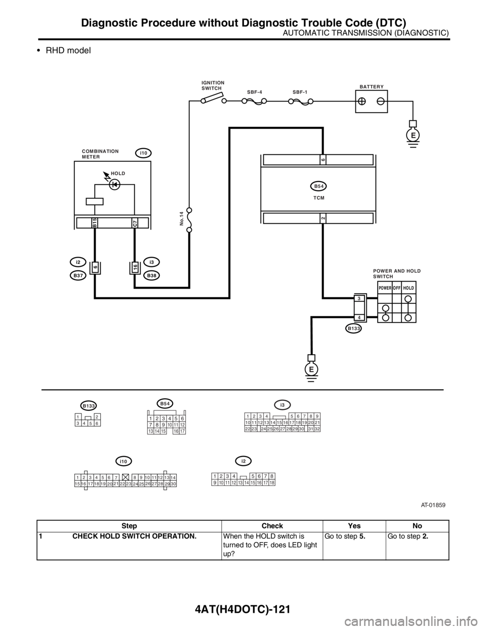
RHD model
Step Check Yes No
1 CHECK HOLD SWITCH OPERATION.When the HOLD switch is
turned to OFF, does LED light
up?Go to step 5.Go to step 2.
AT-01859
SBF-4 SBF-1
No.14
i10
i3
B38
B54
B133
B15
C7
16
E
B54
123456
78 9 10 1112
13
14
15 16 17
1819
2021
2223
24
2526
2728
2930
i10
POWEROFF HOLD
3
4
E
HOLD
i2
B133
12
34
56219
32
i3
1234
56
10 11 12 13 14 157
16
23 3019 20
22 26 27 28 298
17
24 3118
25
6i2
B37
26
POWER AND HOLD
SWITCH IGNITION
SWITCHBATTERY
COMBINATION
METER
TCM
123
8910411 12
13 14 15 1656
7
17
123 8
910411 12 13 14 15 165671718
Page 2698 of 2870

4AT(H4DOTC)-122
AUTOMATIC TRANSMISSION (DIAGNOSTIC)
Diagnostic Procedure without Diagnostic Trouble Code (DTC)
2 CHECK HOLD SWITCH OPERATION.When the HOLD switch is
turned to ON, does LED light
up?Go to step Check
Kick-Down Switch.
124, CHECK
KICK–DOWN
SWITCH, Diagnos-
tic Procedure with-
out Diagnostic
Trouble Code
(DTC).>Go to step 3.
3 CHECK HOLD INDICATOR LIGHT.
1) Turn the ignition switch to OFF.
2) Remove the combination meter.
3) Remove the HOLD indicator light bulb from
combination meter.Is the HOLD indicator light bulb
OK?Go to step 4.Replace the HOLD
indicator light bulb.
Meter Assembly.>
4 CHECK HOLD SWITCH GROUND LINE.
1) Turn the ignition switch to OFF.
2) Disconnect the connector from HOLD switch.
3) Measure the resistance of harness connec-
tor between HOLD switch and chassis ground.
Connector & terminal
LHD model
(R92) No. 4 — Chassis ground:
RHD model
(B133) No. 4 — Chassis ground:Is the resistance less than 1
Ω?Go to step 5.Repair the open
circuit in harness
between HOLD
switch and chas-
sis ground.
5 CHECK HOLD SWITCH.
1) Turn the HOLD switch to ON.
2) Measure the resistance between terminals
of HOLD switch.
Te r m i n a l s
No. 4 — No. 3:Is the resistance less than 1
Ω?Go to step 6.Replace the HOLD
switch.
6 CHECK HOLD SWITCH.
1) Turn the HOLD switch to OFF.
2) Measure the resistance between terminals
of HOLD switch.
Te r m i n a l s
No. 4 — No. 3:Is the resistance more than 1
MΩ?Go to step 7.Replace the HOLD
switch.
7 CHECK HARNESS CONNECTOR BETWEEN
TCM AND HOLD SWITCH.
1) Disconnect the connector TCM and combi-
nation meter.
2) Measure the resistance of harness connec-
tor between TCM and HOLD switch.
Connector & terminal
LHD model
(B54) No. 2 — (R92) No. 3:
RHD model
(B54) No. 2 — (B133) No. 3:Is the resistance less than 1
Ω?Go to step 8.Repair the open
circuit in harness
between TCM and
HOLD switch con-
nector and poor
contact in cou-
pling connector.
8 CHECK HARNESS CONNECTOR BETWEEN
TCM AND COMBINATION METER.
Measure the resistance of harness connector
between TCM and combination meter.
Connector & terminal
(B54) No. 6 — (i10) No. 14:Is the resistance less than 1
Ω?Go to step 9.Repair the open
circuit in harness
between TCM and
combination
meter, and poor
contact in cou-
pling connector. Step Check Yes No
Page 2725 of 2870
5MT-13
MANUAL TRANSMISSION AND DIFFERENTIAL
General Description
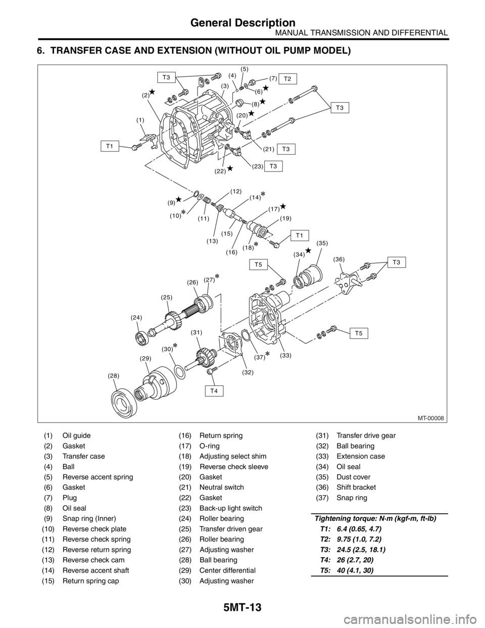
6. TRANSFER CASE AND EXTENSION (WITHOUT OIL PUMP MODEL)
(1) Oil guide (16) Return spring (31) Transfer drive gear
(2) Gasket (17) O-ring (32) Ball bearing
(3) Transfer case (18) Adjusting select shim (33) Extension case
(4) Ball (19) Reverse check sleeve (34) Oil seal
(5) Reverse accent spring (20) Gasket (35) Dust cover
(6) Gasket (21) Neutral switch (36) Shift bracket
(7) Plug (22) Gasket (37) Snap ring
(8) Oil seal (23) Back-up light switch
(9) Snap ring (Inner) (24) Roller bearingTightening torque: N·m (kgf-m, ft-lb)
(10) Reverse check plate (25) Transfer driven gearT1: 6.4 (0.65, 4.7)
(11) Reverse check spring (26) Roller bearingT2: 9.75 (1.0, 7.2)
(12) Reverse return spring (27) Adjusting washerT3: 24.5 (2.5, 18.1)
(13) Reverse check cam (28) Ball bearingT4: 26 (2.7, 20)
(14) Reverse accent shaft (29) Center differentialT5: 40 (4.1, 30)
(15) Return spring cap (30) Adjusting washer
MT-00008
(2)(7)
(6)
(21) (8) (5)
(4)
(3)
(1)
T3 T2
T3
T3
T1
T1
(20)
(9)
(11)
(13)(15) (10)(12)
(17)
(16)(19)
(22)(23)
(14)
(18)
T3
T5
T4(34)
(36) (35)
(33) (27)
(31)(30)
(29)
(28)
(37)
(32)
(24)(25)(26)
T3T5
Page 2726 of 2870
5MT-14
MANUAL TRANSMISSION AND DIFFERENTIAL
General Description
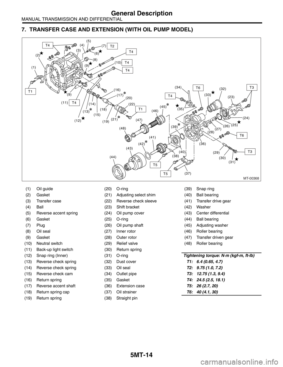
7. TRANSFER CASE AND EXTENSION (WITH OIL PUMP MODEL)
(1) Oil guide (20) O-ring (39) Snap ring
(2) Gasket (21) Adjusting select shim (40) Ball bearing
(3) Transfer case (22) Reverse check sleeve (41) Transfer drive gear
(4) Ball (23) Shift bracket (42) Washer
(5) Reverse accent spring (24) Oil pump cover (43) Center differential
(6) Gasket (25) O-ring (44) Ball bearing
(7) Plug (26) Oil pump shaft (45) Adjusting washer
(8) Oil seal (27) Inner rotor (46) Roller bearing
(9) Gasket (28) Outer rotor (47) Transfer driven gear
(10) Neutral switch (29) Relief valve (48) Roller bearing
(11) Back-up light switch (30) Return spring
(12) Snap ring (Inner) (31) O-ringTightening torque: N·m (kgf-m, ft-lb)
(13) Reverse check spring (32) Dust coverT1: 6.4 (0.65, 4.7)
(14) Reverse check spring (33) Oil sealT2: 9.75 (1.0, 7.2)
(15) Reverse check cam (34) Outlet pipeT3: 12.75 (1.3, 9.4)
(16) Return spring (35) GasketT4: 24.5 (2.5, 18.1)
(17) Reverse accent shaft (36) Extension caseT5: 26 (2.7, 20)
(18) Return spring cap (37) Oil strainerT6: 40 (4.1, 30)
(19) Return spring (38) Straight pin
MT-00368
(2)(7)
(6)
(10) (8) (5)
(4)
(3)
(1)
T4
T4
T2
T4
T4
(11)
T4
T4
T3
T3
T6
T6
T5
T5
T1
T1
(9)
(12)(14)
(15)(18)
(13)(16)
(20)
(19)(22)
(33)
(23)
(24) (32)
(25)
(26)
(27)
(28)
(36)
(31) (30) (29)
(37)
(35)
(9)(17)
(45)
(41)
(42)
(43)
(44)
(39)
(38)(40)
(21)
(48)(47)(46)(34)
Page 2729 of 2870
5MT-17
MANUAL TRANSMISSION AND DIFFERENTIAL
General Description
C: CAUTION
Wear working clothing, including a cap, protec-
tive goggles, and protective shoes during opera-
tion.
Remove contamination including dirt and corro-
sion before removal, installation, and disassembly.
Keep the disassembled parts in order and pro-
tect them from dust or dirt.
Until the oil pan is removed, do not place with the
oil pan side facing up to prevent foreign matter from
entering the valve body.
Before removal, installation or disassembly, be
sure to clarify the failure. Avoid unnecessary re-
moval, installation, disassembly and replacement.
When disassembling the case and other light al-
loy parts, use a plastic hammer to force it apart. Do
not pry it apart with a screwdriver or other tool.
Be careful not to burn your hands, because each
part on the vehicle is hot after running. Use SUBARU genuine gear oil, grease etc. or
the equivalent. Do not mix gear oil, grease etc. with
that of another grade or from other manufacturers.
Be sure to tighten fasteners including bolts and
nuts to the specified torque.
Place shop jacks or rigid racks at the specified
points.
Apply gear oil onto sliding or revolution surfaces
before installation.
Replace deformed or otherwise damaged snap
rings with new ones.
Before installing O-rings or oil seals, apply suffi-
cient amount of gear oil to avoid damage and defor-
mation.
Be careful not to incorrectly install or fail to install
O-rings, snap rings and other such parts.
Before securing a part on a vise, place cushion-
ing material such as wood blocks, aluminum plate,
or shop cloth between the part and the vis e.
Avoid damaging the mating surface of the case.
Before applying sealant, completely remove the
old seal.
D: PREPARATION TOOL
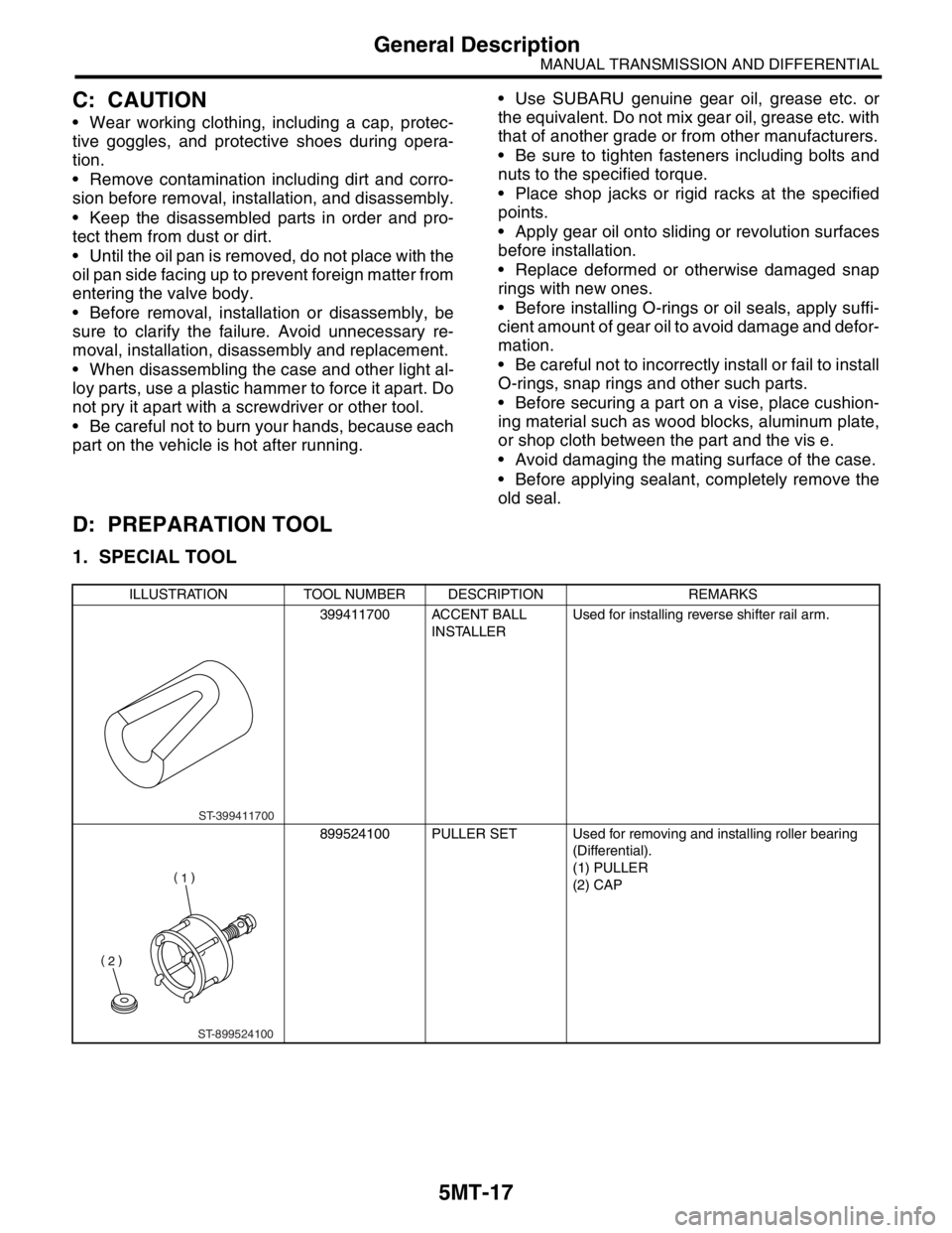
1. SPECIAL TOOL
ILLUSTRATION TOOL NUMBER DESCRIPTION REMARKS
399411700 ACCENT BALL
INSTALLERUsed for installing reverse shifter rail arm.
899524100 PULLER SET Used for removing and installing roller bearing
(Differential).
(1) PULLER
(2) CAP
ST-399411700
ST-899524100
Page 2744 of 2870
5MT-32
MANUAL TRANSMISSION AND DIFFERENTIAL
Manual Transmission Assembly
3. Manual Transmission As-
sembly
A: REMOVAL
1) Set the vehicle on a lift.
2) Disconnect the ground cable from battery.
3) Drain the transmission gear oil completely.
Oil.>
4) Open the front hood fully, and support with stay.
5) Remove the air intake duct and air cleaner case.
(Non-turbo model)
6) Remove the air cleaner case stay. (Non-turbo
model)
7) Remove the intercooler. (Turbo model)
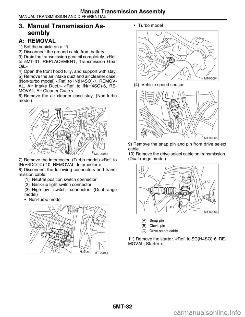
8) Disconnect the following connectors and trans-
mission cable.
(1) Neutral position switch connector
(2) Back-up light switch connector
(3) High-low switch connector (Dual-range
model)
Non-turbo model Turbo model
(4) Vehicle speed sensor
9) Remove the snap pin and pin from drive select
cable.
10) Remove the drive select cable on transmission.
(Dual-range model)
11) Remove the starter.
ME-00062
MT-00063
(A) Snap pin
(B) Clevis pin
(C) Drive select cable
MT-00064
MT-00065
MT-00066
(A)
(B)
(C)
Page 2750 of 2870
5MT-38
MANUAL TRANSMISSION AND DIFFERENTIAL
Manual Transmission Assembly
24) Push clutch release lever to fit bearing into
clutch cover.
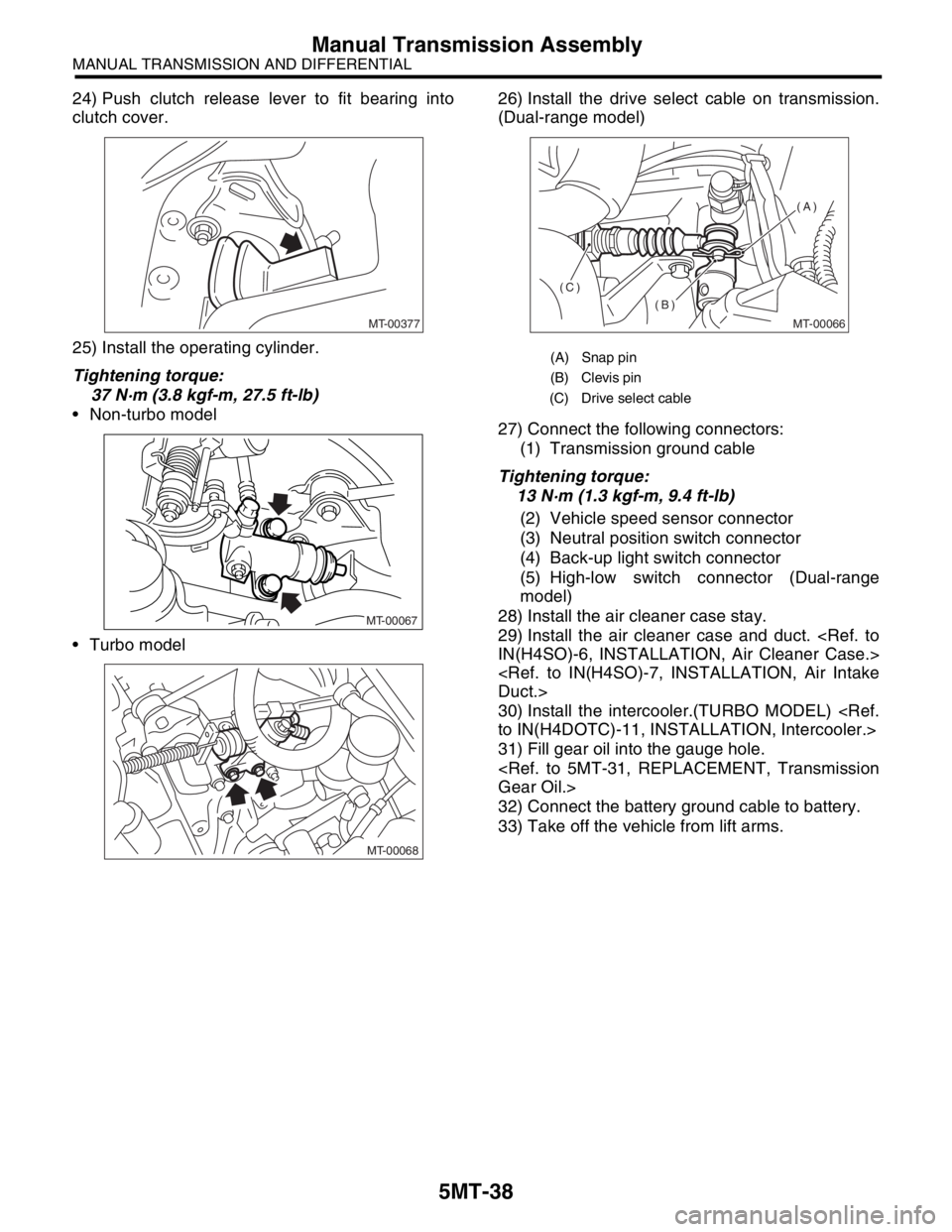
25) Install the operating cylinder.
Tightening torque:
37 N·m (3.8 kgf-m, 27.5 ft-lb)
Non-turbo model
Turbo model26) Install the drive select cable on transmission.
(Dual-range model)
27) Connect the following connectors:
(1) Transmission ground cable
Tightening torque:
13 N·m (1.3 kgf-m, 9.4 ft-lb)
(2) Vehicle speed sensor connector
(3) Neutral position switch connector
(4) Back-up light switch connector
(5) High-low switch connector (Dual-range
model)
28) Install the air cleaner case stay.
29) Install the air cleaner case and duct.
30) Install the intercooler.(TURBO MODEL)
31) Fill gear oil into the gauge hole.
32) Connect the battery ground cable to battery.
33) Take off the vehicle from lift arms.
MT-00377
MT-00067
MT-00068
(A) Snap pin
(B) Clevis pin
(C) Drive select cable
MT-00066
(A)
(B)
(C)