2004 SUBARU FORESTER light
[x] Cancel search: lightPage 2774 of 2870
5MT-61
MANUAL TRANSMISSION AND DIFFERENTIAL
Reverse Check Sleeve
E: INSPECTION
Make sure the cutout section of reverse accent
shaft is aligned with the opening in reverse check
sleeve.
Spin the cam by hand for smooth rotation.
Move the cam and shaft all the way toward plate
and release.
If the cam does not return properly, replace the re-
verse check spring; if shaft does not, check for
scratches on the inner surface of sleeve. If sleeve
is in good order, replace the spring.
Select a suitable reverse accent shaft and re-
verse check plate.
F: ADJUSTMENT
1. NEUTRAL POSITION ADJUSTMENT
1) Shift the gear into 3rd gear position.
2) Shifter arm turns lightly toward the 1st/2nd gear
side but heavily toward the reverse gear side be-
cause of the function of return spring, until arm con-
tacts the stopper.
3) Make adjustment so that the heavy stroke (re-
verse side) is a little more than the light stroke (1st/
2nd side).
4) To adjust, remove the bolts holding reverse
check sleeve assembly to the case, move the
sleeve assembly outward, and place adjusting
shim (0 to 1 ea.) between sleeve assembly and
case to adjust the clearance.5) Be careful not to break the O-ring when placing
shim(s).
NOTE:
When the shim is removed, the neutral position
will move closer to reverse; when shim is added,
the neutral position will move closer to 1st gear.
If the shims alone cannot adjust clearance, re-
place the reverse accent shaft and re-adjust.
2. REVERSE CHECK PLATE ADJUST-
MENT
1) Shift the shifter arm to “5th” and then to reverse
to see if reverse check mechanism operates prop-
erly.
2) Also check to see if the arm returns to neutral
when released from reverse position. If the arm
does not return properly, replace the reverse check
plate.
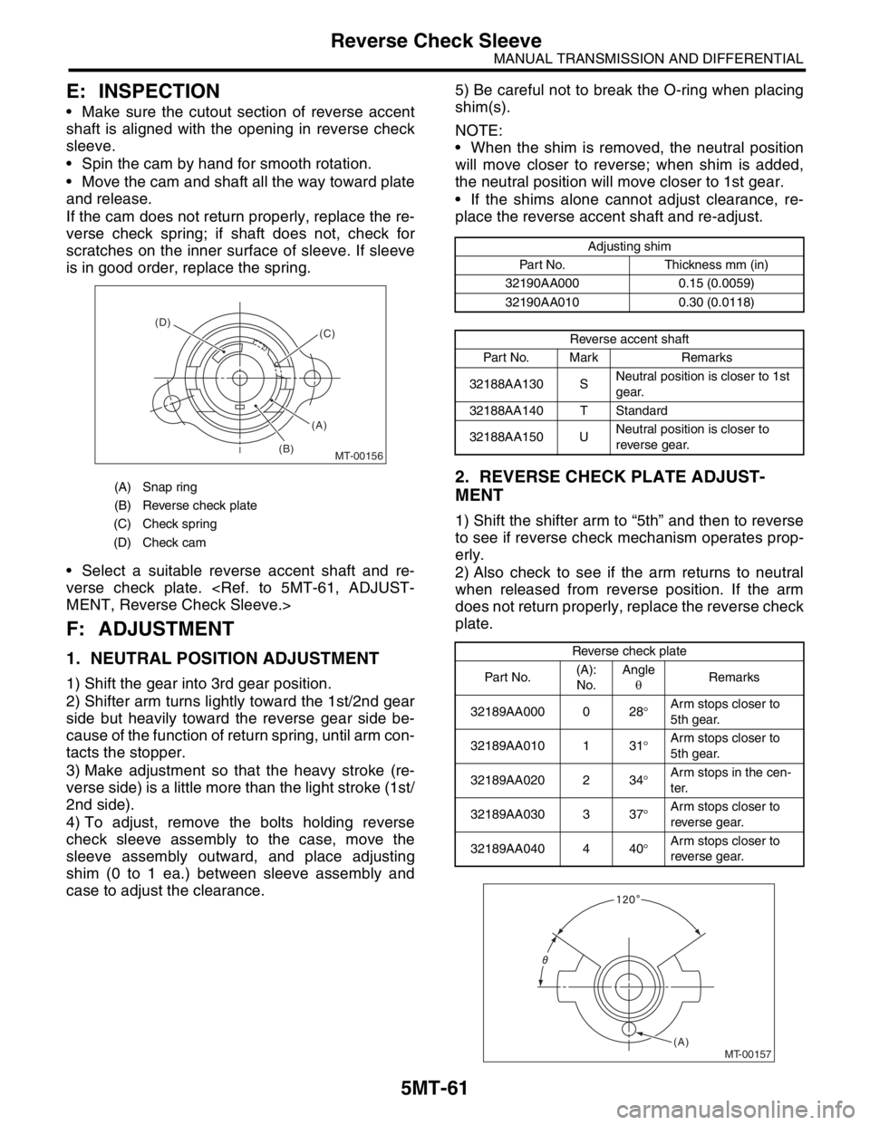
(A) Snap ring
(B) Reverse check plate
(C) Check spring
(D) Check cam
MT-00156
(A) (D)
(B)(C)
Adjusting shim
Part No. Thickness mm (in)
32190AA000 0.15 (0.0059)
32190AA010 0.30 (0.0118)
Reverse accent shaft
Part No. Mark Remarks
32188AA130 SNeutral position is closer to 1st
gear.
32188AA140 T Standard
32188AA150 UNeutral position is closer to
reverse gear.
Reverse check plate
Par t No.(A):
No.Angle
θRemarks
32189AA000 0 28°Arm stops closer to
5th gear.
32189AA010 1 31°Arm stops closer to
5th gear.
32189AA020 2 34°Arm stops in the cen-
ter.
32189AA030 3 37°Arm stops closer to
reverse gear.
32189AA040 4 40°Arm stops closer to
reverse gear.
MT-00157(A)
Page 2778 of 2870
5MT-65
MANUAL TRANSMISSION AND DIFFERENTIAL
Transmission Case
8) Backlash adjustment of hypoid gear and preload
adjustment of roller bearing:
NOTE:
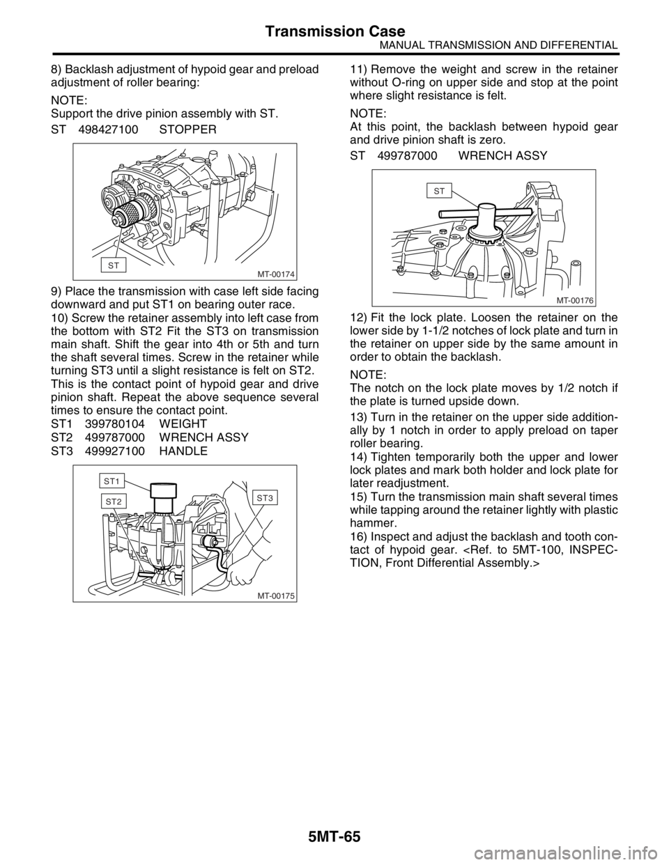
Support the drive pinion assembly with ST.
ST 498427100 STOPPER
9) Place the transmission with case left side facing
downward and put ST1 on bearing outer race.
10) Screw the retainer assembly into left case from
the bottom with ST2 Fit the ST3 on transmission
main shaft. Shift the gear into 4th or 5th and turn
the shaft several times. Screw in the retainer while
turning ST3 until a slight resistance is felt on ST2.
This is the contact point of hypoid gear and drive
pinion shaft. Repeat the above sequence several
times to ensure the contact point.
ST1 399780104 WEIGHT
ST2 499787000 WRENCH ASSY
ST3 499927100 HANDLE11) Remove the weight and screw in the retainer
without O-ring on upper side and stop at the point
where slight resistance is felt.
NOTE:
At this point, the backlash between hypoid gear
and drive pinion shaft is zero.
ST 499787000 WRENCH ASSY
12) Fit the lock plate. Loosen the retainer on the
lower side by 1-1/2 notches of lock plate and turn in
the retainer on upper side by the same amount in
order to obtain the backlash.
NOTE:
The notch on the lock plate moves by 1/2 notch if
the plate is turned upside down.
13) Turn in the retainer on the upper side addition-
ally by 1 notch in order to apply preload on taper
roller bearing.
14) Tighten temporarily both the upper and lower
lock plates and mark both holder and lock plate for
later readjustment.
15) Turn the transmission main shaft several times
while tapping around the retainer lightly with plastic
hammer.
16) Inspect and adjust the backlash and tooth con-
tact of hypoid gear.
MT-00174ST
MT-00175
ST3ST2
ST1
MT-00176
ST
Page 2780 of 2870
5MT-67
MANUAL TRANSMISSION AND DIFFERENTIAL
Transmission Case
8) Tighten the input shaft holder attaching bolts.
Tightening torque:
20 N·m (2.0 kgf-m, 14.5 ft-lb)
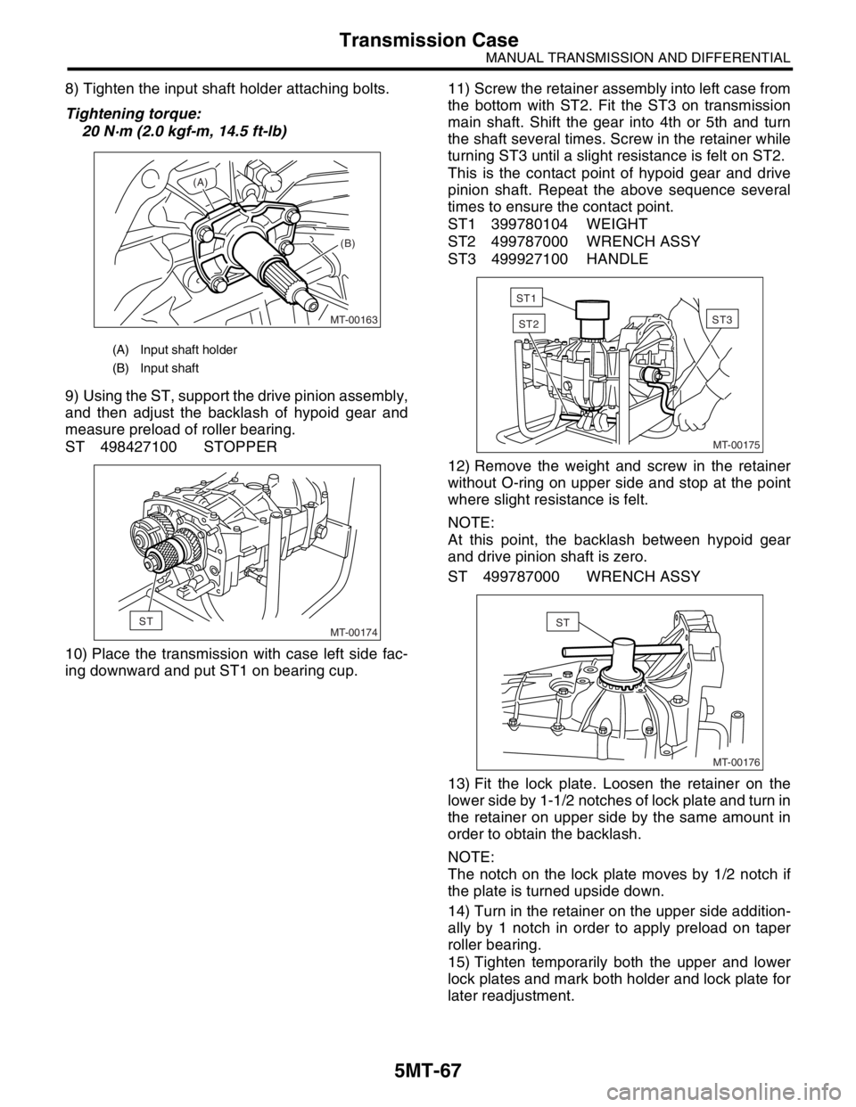
9) Using the ST, support the drive pinion assembly,
and then adjust the backlash of hypoid gear and
measure preload of roller bearing.
ST 498427100 STOPPER
10) Place the transmission with case left side fac-
ing downward and put ST1 on bearing cup.11) Screw the retainer assembly into left case from
the bottom with ST2. Fit the ST3 on transmission
main shaft. Shift the gear into 4th or 5th and turn
the shaft several times. Screw in the retainer while
turning ST3 until a slight resistance is felt on ST2.
This is the contact point of hypoid gear and drive
pinion shaft. Repeat the above sequence several
times to ensure the contact point.
ST1 399780104 WEIGHT
ST2 499787000 WRENCH ASSY
ST3 499927100 HANDLE
12) Remove the weight and screw in the retainer
without O-ring on upper side and stop at the point
where slight resistance is felt.
NOTE:
At this point, the backlash between hypoid gear
and drive pinion shaft is zero.
ST 499787000 WRENCH ASSY
13) Fit the lock plate. Loosen the retainer on the
lower side by 1-1/2 notches of lock plate and turn in
the retainer on upper side by the same amount in
order to obtain the backlash.
NOTE:
The notch on the lock plate moves by 1/2 notch if
the plate is turned upside down.
14) Turn in the retainer on the upper side addition-
ally by 1 notch in order to apply preload on taper
roller bearing.
15) Tighten temporarily both the upper and lower
lock plates and mark both holder and lock plate for
later readjustment.
(A) Input shaft holder
(B) Input shaft
MT-00163
(A)
(B)
MT-00174ST
MT-00175
ST3ST2
ST1
MT-00176
ST
Page 2781 of 2870
5MT-68
MANUAL TRANSMISSION AND DIFFERENTIAL
Transmission Case
16) Turn the transmission main shaft several times
while tapping around the retainer lightly with plastic
hammer.
17) Inspect and adjust the backlash and tooth con-
tact of hypoid gear.
18) After checking the tooth contact of hypoid
gears, remove the lock plate. Then loosen the re-
tainer until the O-ring groove appears. Fit the O-
ring into groove and tighten the retainer into the po-
sition where retainer has been tightened in.
Tighten the lock plate.
NOTE:
Carry out this job on both upper and lower retain-
ers.
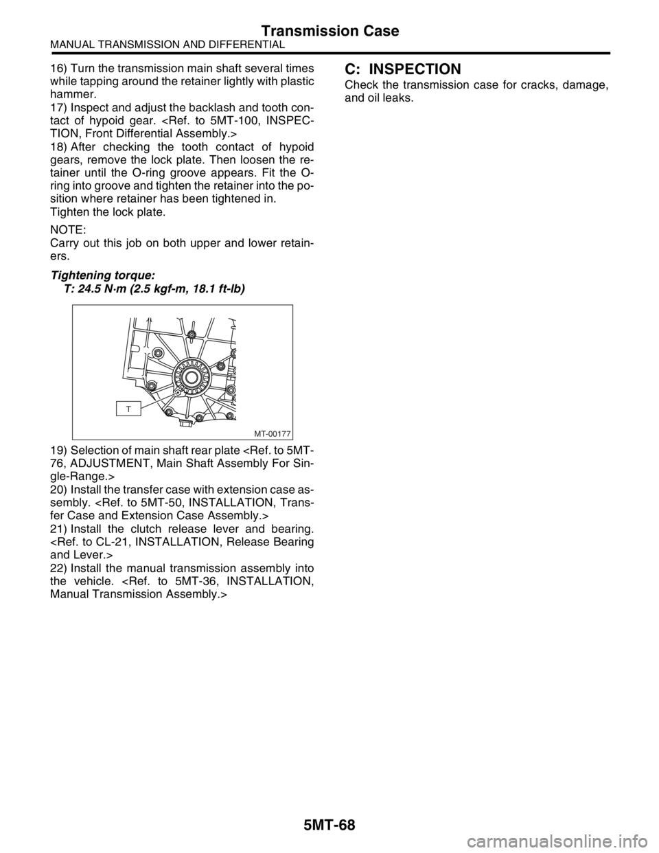
Tightening torque:
T: 24.5 N·m (2.5 kgf-m, 18.1 ft-lb)
19) Selection of main shaft rear plate
gle-Range.>
20) Install the transfer case with extension case as-
sembly.
21) Install the clutch release lever and bearing.
22) Install the manual transmission assembly into
the vehicle.
Check the transmission case for cracks, damage,
and oil leaks.
MT-00177
T
Page 2789 of 2870
5MT-76
MANUAL TRANSMISSION AND DIFFERENTIAL
Main Shaft Assembly For Single-Range
E: INSPECTION
Disassembled parts should be washed clean first
and then inspected carefully.
1) Bearings
Replace the bearings in the following cases:
Bearings whose balls, outer races and inner rac-
es are broken or rusty.
Worn bearings
Bearings that fail to turn smoothly or make noise
when turned after gear oil lubrication.
Bearings having other defects
2) Bushing (each gear)
Replace the bushing in the following cases:
When the sliding surface is damaged or abnor-
mally worn.
When the inner wall is abnormally worn.
3) Gears
Replace the gears with new ones if their tooth
surfaces are broken, damaged, or excessively
worn.
Correct or replace if the cone that contacts the
baulk ring is rough or damaged.
Correct or replace if the inner surface or end face
is damaged.
4) Baulk ring
Replace the ring in the following cases:
When the inner surface and end face are dam-
aged.
When the ring inner surface is abnormally or par-
tially worn down.
When the contact surface of the synchronizer
ring insert is scored or abnormally worn down.
5) Shifting insert key
Replace the insert if deformed, excessively worn,
or defective in any way.
6) Oil seal
Replace the oil seal if the lip is deformed, hard-
ened, damaged, worn, or defective in any way.
7) O-ring
Replace the O-ring if the sealing face is deformed,
hardened, damaged, worn, or defective in any way.
8) Gearshift mechanism
Repair or replace the gearshift mechanism if ex-
cessively worn, bent, or defective in any way.
F: ADJUSTMENT
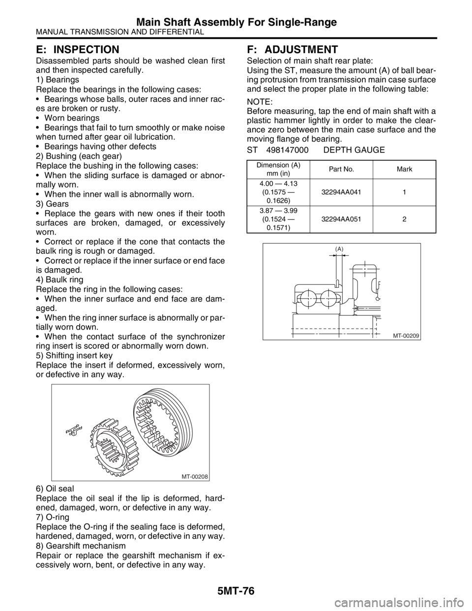
Selection of main shaft rear plate:
Using the ST, measure the amount (A) of ball bear-
ing protrusion from transmission main case surface
and select the proper plate in the following table:
NOTE:
Before measuring, tap the end of main shaft with a
plastic hammer lightly in order to make the clear-
ance zero between the main case surface and the
moving flange of bearing.
ST 498147000 DEPTH GAUGE
MT-00208
Dimension (A)
mm (in)Par t No. Mar k
4.00 — 4.13
(0.1575 —
0.1626)32294AA041 1
3.87 — 3.99
(0.1524 —
0.1571)32294AA051 2
MT-00209
(A)
Page 2798 of 2870
5MT-85
MANUAL TRANSMISSION AND DIFFERENTIAL
Input Shaft Assembly
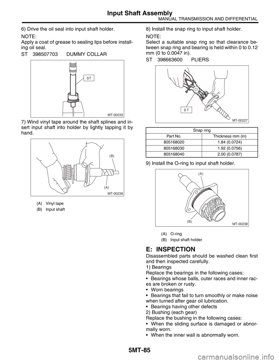
6) Drive the oil seal into input shaft holder.
NOTE:
Apply a coat of grease to sealing lips before install-
ing oil seal.
ST 398507703 DUMMY COLLAR
7) Wind vinyl tape around the shaft splines and in-
sert input shaft into holder by lightly tapping it by
hand.8) Install the snap ring to input shaft holder.
NOTE:
Select a suitable snap ring so that clearance be-
tween snap ring and bearing is held within 0 to 0.12
mm (0 to 0.0047 in).
ST 398663600 PLIERS
9) Install the O-ring to input shaft holder.
E: INSPECTION
Disassembled parts should be washed clean first
and then inspected carefully.
1) Bearings
Replace the bearings in the following cases:
Bearings whose balls, outer races and inner rac-
es are broken or rusty.
Worn bearings
Bearings that fail to turn smoothly or make noise
when turned after gear oil lubrication.
Bearings having other defects
2) Bushing (each gear)
Replace the bushing in the following cases:
When the sliding surface is damaged or abnor-
mally worn.
When the inner wall is abnormally worn.
(A) Vinyl tape
(B) Input shaft
MT-00235
ST
MT-00236
(A)(B)
Snap ring
Part No. Thickness mm (in)
805168020 1.84 (0.0724)
805168030 1.92 (0.0756)
805168040 2.00 (0.0787)
(A) O-ring
(B) Input shaft holder
MT-00227
ST
MT-00238
(A)
(B)
Page 2806 of 2870
5MT-93
MANUAL TRANSMISSION AND DIFFERENTIAL
Drive Pinion Shaft Assembly
E: INSPECTION
Disassembled parts should be washed clean first
and then inspected carefully.
1) Bearings
Replace the bearings in the following cases:
Bearings whose balls, outer races and inner rac-
es are broken or rusty.
Worn bearings
Bearings that fail to turn smoothly or make noise
when turned after gear oil lubrication.
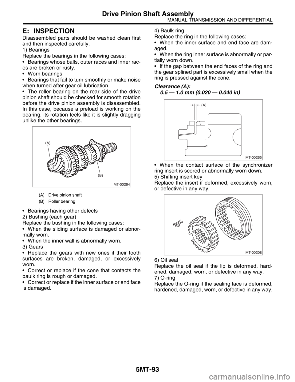
The roller bearing on the rear side of the drive
pinion shaft should be checked for smooth rotation
before the drive pinion assembly is disassembled.
In this case, because a preload is working on the
bearing, its rotation feels like it is slightly dragging
unlike the other bearings.
Bearings having other defects
2) Bushing (each gear)
Replace the bushing in the following cases:
When the sliding surface is damaged or abnor-
mally worn.
When the inner wall is abnormally worn.
3) Gears
Replace the gears with new ones if their tooth
surfaces are broken, damaged, or excessively
worn.
Correct or replace if the cone that contacts the
baulk ring is rough or damaged.
Correct or replace if the inner surface or end face
is damaged.4) Baulk ring
Replace the ring in the following cases:
When the inner surface and end face are dam-
aged.
When the ring inner surface is abnormally or par-
tially worn down.
If the gap between the end faces of the ring and
the gear splined part is excessively small when the
ring is pressed against the cone.
Clearance (A):
0.5 — 1.0 mm (0.020 — 0.040 in)
When the contact surface of the synchronizer
ring insert is scored or abnormally worn down.
5) Shifting insert key
Replace the insert if deformed, excessively worn,
or defective in any way.
6) Oil seal
Replace the oil seal if the lip is deformed, hard-
ened, damaged, worn, or defective in any way.
7) O-ring
Replace the O-ring if the sealing face is deformed,
hardened, damaged, worn, or defective in any way.
(A) Drive pinion shaft
(B) Roller bearing
MT-00264
(A)
(B)
MT-00265
(A)
MT-00208
Page 2814 of 2870

5MT-101
MANUAL TRANSMISSION AND DIFFERENTIAL
Front Differential Assembly
3. TOOTH CONTACT OF HYPOID GEAR
Check the tooth contact of hypoid gear as follows:
Apply a uniform thin coat of red lead on both tooth
surfaces of 3 or 4 teeth of the hypoid gear. Move
the hypoid gear back and forth by turning the trans-
mission main shaft until a definite contact pattern is
developed on hypoid gear, and judge whether face
contact is correct. If it is inaccurate, make adjust-
ment.
Tooth contact is correct.
F: ADJUSTMENT
1. BEVEL PINION GEAR BACKLASH
1) Disassemble the front differential.
2) Select a different washer from the table and in-
stall.
3) Adjust until the specified value is obtained.
Standard backlash:
0.13 — 0.18 mm (0.0051 — 0.0071 in)
2. HYPOID GEAR BACKLASH
Adjust backlash by turning the holder in right side
case.
ST 499787000 WRENCH ASSY
NOTE:
Each time holder rotates one tooth, backlash
changes by 0.05 mm (0.0020 in).
3. TOOTH CONTACT OF HYPOID GEAR
1) Adjust until the teeth contact is correct.
2) Check and adjust the teeth contact with following
table.
Tooth contact
Checking item:Tooth contact pattern is slightly
shifted toward to toe side under no-load
rotation. [When loaded, contact pattern moves
toward heel.]
(A) Toe
(B) Coast side
(C) Heel
(D) Drive side
Washer
Part No. Thickness mm (in)
8030380210.925 — 0.950
(0.0364 — 0.0374)
8030380220.975 — 1.000
(0.0384 — 0.0394)
803038023 1.025 — 1.050
(0.0404 — 0.0413)
MT-00294
(A)
(B) (C)
(D)
(A) Toe side
(B) Heel side
MT-00176
ST
MT-00296
0.05mm(0.0020 in)
AT-00207
(A)
(B)