2004 SUBARU FORESTER light
[x] Cancel search: lightPage 329 of 2870
FUJI HEAVY INDUSTRIES LTD. G8080GE7
2004 FORESTER SERVICE MANUAL QUICK REFERENCE INDEX
BODY SECTION
This service manual has been prepared
to provide SUBARU service personnel
with the necessary information and data
for the correct maintenance and repair
of SUBARU vehicles.
This manual includes the procedures
for maintenance, disassembling, reas-
sembling, inspection and adjustment of
components and diagnostics for guid-
ance of experienced mechanics.
Please peruse and utilize this manual
fully to ensure complete repair work for
satisfying our customers by keeping
their vehicle in optimum condition.
When replacement of parts during
repair work is needed, be sure to use
SUBARU genuine parts.
All information, illustration and specifi-
cations contained in this manual are
based on the latest product information
available at the time of publication
approval.HVAC SYSTEM
(HEATER, VENTILATOR AND A/C)AC
HVAC SYSTEM (AUTO A/C)
(DIAGNOSTIC)AC
AIRBAG SYSTEM AB
AIRBAG SYSTEM (DIAGNOSTIC) AB
SEAT BELT SYSTEM SB
LIGHTING SYSTEM LI
WIPER AND WASHER SYSTEM WW
ENTERTAINMENT ET
COMMUNICATION SYSTEM COM
GLASS/WINDOW/MIRROR GW
BODY STRUCTURE BS
INSTRUMENTATION/DRIVER INFO IDI
SEAT SE
SECURITY AND LOCK SL
SUNROOF/T-TOP/CONVERTIBLE TOP
(SUNROOF)SR
EXTERIOR/INTERIOR TRIM EI
EXTERIOR BODY PANEL EB
Page 349 of 2870
GW-19
GLASS/WINDOW/MIRROR
Front Door Glass
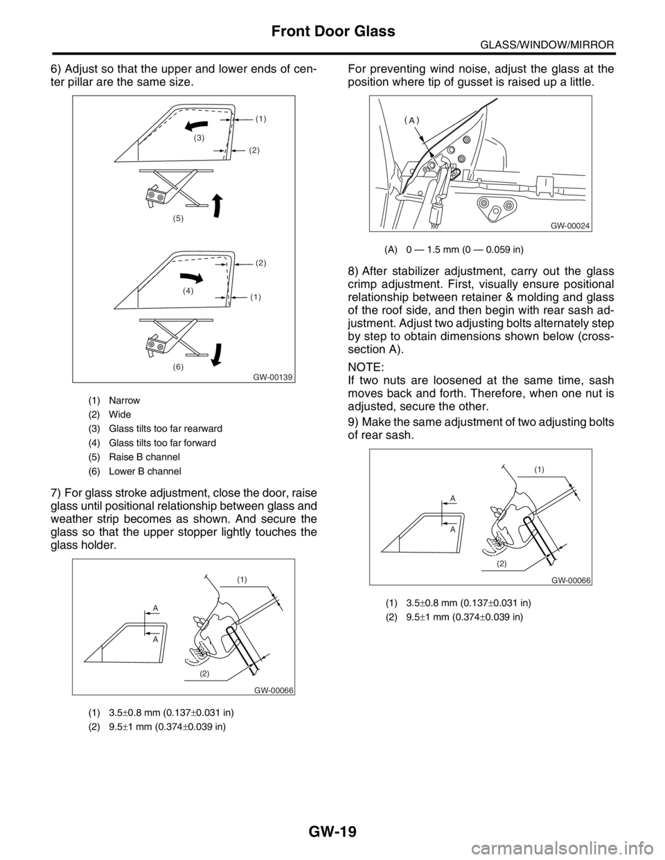
6) Adjust so that the upper and lower ends of cen-
ter pillar are the same size.
7) For glass stroke adjustment, close the door, raise
glass until positional relationship between glass and
weather strip becomes as shown. And secure the
glass so that the upper stopper lightly touches the
glass holder.For preventing wind noise, adjust the glass at the
position where tip of gusset is raised up a little.
8) After stabilizer adjustment, carry out the glass
crimp adjustment. First, visually ensure positional
relationship between retainer & molding and glass
of the roof side, and then begin with rear sash ad-
justment. Adjust two adjusting bolts alternately step
by step to obtain dimensions shown below (cross-
section A).
NOTE:
If two nuts are loosened at the same time, sash
moves back and forth. Therefore, when one nut is
adjusted, secure the other.
9) Make the same adjustment of two adjusting bolts
of rear sash.
(1) Narrow
(2) Wide
(3) Glass tilts too far rearward
(4) Glass tilts too far forward
(5) Raise B channel
(6) Lower B channel
(1) 3.5±0.8 mm (0.137±0.031 in)
(2) 9.5±1 mm (0.374±0.039 in)
GW-00139 (6) (5)
(4)
(1)(2) (1)
(2) (3)
A
A
(1)
(2)
GW-00066
(A) 0 — 1.5 mm (0 — 0.059 in)
(1) 3.5±0.8 mm (0.137±0.031 in)
(2) 9.5±1 mm (0.374±0.039 in)
GW-00024
A
A
(1)
(2)
GW-00066
Page 357 of 2870
GW-27
GLASS/WINDOW/MIRROR
Windshield Glass
6) Apply primer to the adhesive layer of glass using
sponge.
Glass primer:
Dow Automotive
U-401 or U-402
7) Apply primer to the adhesive layer of body.
Painted surface primer:
Dow Automotive
U-413
NOTE:
Primer once attached to the painted surface of
the body and internal trim is hard to wipe off. Mask
the circumference of such areas.
Let the primer dry for about ten minutes before
installing the glass.
Do not touch the surface coated with primer.
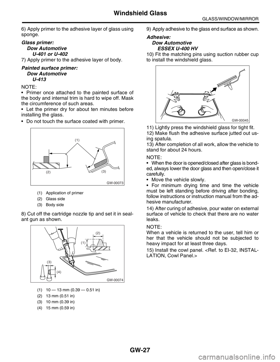
8) Cut off the cartridge nozzle tip and set it in seal-
ant gun as shown.9) Apply adhesive to the glass end surface as shown.
Adhesive:
Dow Automotive
ESSEX U-400 HV
10) Fit the matching pins using suction rubber cup
to install the windshield glass.
11) Lightly press the windshield glass for tight fit.
12) Make flush the adhesive surface jutted out us-
ing spatula.
13) After completion of all work, allow the vehicle to
stand for about 24 hours.
NOTE:
When the door is opened/closed after glass is bond-
ed, always lower the door glass and then open/close it
carefully.
Move the vehicle slowly.
For minimum drying time and time the vehicle
must be left standing before driving after bonding,
follow instructions or instruction manual from the ad-
hesive manufacturer.
14) After curing of adhesive, pour water on external
surface of vehicle to check that there are no water
leaks.
NOTE:
When a vehicle is returned to the user, tell him or
her that the vehicle should not be subjected to
heavy impact for at least three days.
15) Install the cowl panel.
(1) Application of primer
(2) Glass side
(3) Body side
(1) 10 — 13 mm (0.39 — 0.51 in)
(2) 13 mm (0.51 in)
(3) 10 mm (0.39 in)
(4) 15 mm (0.59 in)
(3)
(2)(1)
GW-00073
GW-00074
(1)(2)
(3)
(4)
GW-00045
Page 365 of 2870
FUJI HEAVY INDUSTRIES LTD. G8080GE7
2004 FORESTER SERVICE MANUAL QUICK REFERENCE INDEX
BODY SECTION
This service manual has been prepared
to provide SUBARU service personnel
with the necessary information and data
for the correct maintenance and repair
of SUBARU vehicles.
This manual includes the procedures
for maintenance, disassembling, reas-
sembling, inspection and adjustment of
components and diagnostics for guid-
ance of experienced mechanics.
Please peruse and utilize this manual
fully to ensure complete repair work for
satisfying our customers by keeping
their vehicle in optimum condition.
When replacement of parts during
repair work is needed, be sure to use
SUBARU genuine parts.
All information, illustration and specifi-
cations contained in this manual are
based on the latest product information
available at the time of publication
approval.HVAC SYSTEM
(HEATER, VENTILATOR AND A/C)AC
HVAC SYSTEM (AUTO A/C)
(DIAGNOSTIC)AC
AIRBAG SYSTEM AB
AIRBAG SYSTEM (DIAGNOSTIC) AB
SEAT BELT SYSTEM SB
LIGHTING SYSTEM LI
WIPER AND WASHER SYSTEM WW
ENTERTAINMENT ET
COMMUNICATION SYSTEM COM
GLASS/WINDOW/MIRROR GW
BODY STRUCTURE BS
INSTRUMENTATION/DRIVER INFO IDI
SEAT SE
SECURITY AND LOCK SL
SUNROOF/T-TOP/CONVERTIBLE TOP
(SUNROOF)SR
EXTERIOR/INTERIOR TRIM EI
EXTERIOR BODY PANEL EB
Page 370 of 2870

BS-4
BODY STRUCTURE
Datum Points
(1) Radiator panel gauge hole 6 mm
(0.24 in) dia. (Vehicle center)(14) Fender attaching hole 10 mm
(0.39 in) dia. (Symmetrical)(31) Harness attaching hole 7 mm
(0.28 in) dia. (Symmetrical)
(2) Radiator attaching hole 12 mm
(0.47 in) dia.(15) Fender attaching hole 10 mm
(0.39 in) dia. (Symmetrical)(32) Trim attaching hole 8.5 mm (0.33
in) dia. (Symmetrical)
(3) Headlight attaching hole 7 mm
(0.28 in) dia. (Symmetrical)(16) Front door hinge attaching hole 12
mm (0.47 in) dia. (Symmetrical)(33) Trim attaching hole 7 mm (0.28 in)
dia. (Symmetrical)
(4) Frame plate gauge hole 8 mm
(0.31 in) dia. (Symmetrical)(17) Front door hinge attaching hole 12
mm (0.47 in) dia. (Symmetrical)(34) Harness attaching hole 7×7 mm
(0.28×0.28 in) (Symmetrical)
(5) Bumper beam attaching hole 11
mm (0.43 in) dia. (Symmetrical)(20) Front door switch attaching hole
4.1 mm (0.16 in) dia. (Symmetri-
cal)(35) Tonneau cover bracket attaching
hole 5.5 mm (0.22 in) dia. (Sym-
metrical)
(6) Fender attaching hole 7 mm (0.28
in) dia. (Symmetrical)
(21) Rear door hinge attaching hole 12
mm (0.47 in) dia. (Symmetrical)(36) Rear strut attaching hole 10 mm
(0.39 in) (Symmetrical)
(7) Fender attaching hole 9 mm (0.35
in) dia. (Symmetrical)
(22) Rear door hinge attaching hole 12
mm (0.47 in) dia. (Symmetrical)(37) Floor mat attaching hole 8 mm
(0.31 in) dia.
(8) Power steering tank attaching hole
RH ATF cooler pipe attaching hole
LH 9 mm (0.35 in) dia.(23) Front weather strip attaching hole
5.2 mm (0.20 in) dia. (Symmetri-
cal)(38) Trim attaching hole 9×9 mm
(0.35×0.35 in) (Symmetrical)
(9) Fender attaching hole 10 mm
(0.39 in) dia. (Symmetrical)(39) Trim attaching hole 8 mm (0.31 in)
dia. (Symmetrical)
(25) Rear weather strip attaching hole
5.2 mm (0.20 in) dia. (Symmetri-
cal) (10) Fender attaching hole 7 mm (0.28
in) dia. (Symmetrical)(40) Trim attaching hole 8 mm (0.31 in)
dia. (Symmetrical)
(11) Modular bracket gauge hole 8 mm
(0.31 in) dia. (Vehicle center)(26) Rear door switch attaching hole
4.1 mm (0.16 in) dia. (Symmetri-
cal)
(12) Front strut attaching hole 9.5 mm
(0.37 in) dia. (Symmetrical)
(29) Trim attaching hole 8.5 mm (0.33
in) dia. (Symmetrical)
(13) Front glass attaching hole LH
6.5×10.5 mm (0.26×0.41 in) RH
6.5×7 mm (0.26×0.28 in)(30) Pad attaching hole 5 mm (0.20 in)
dia. (Symmetrical)
Page 371 of 2870
BS-5
BODY STRUCTURE
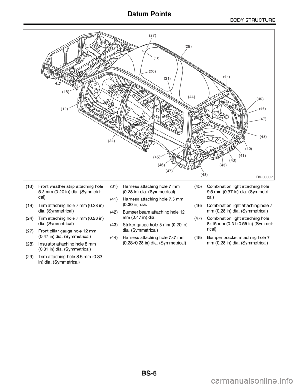
Datum Points
(18) Front weather strip attaching hole
5.2 mm (0.20 in) dia. (Symmetri-
cal)(31) Harness attaching hole 7 mm
(0.28 in) dia. (Symmetrical)(45) Combination light attaching hole
9.5 mm (0.37 in) dia. (Symmetri-
cal)
(41) Harness attaching hole 7.5 mm
(0.30 in) dia.
(19) Trim attaching hole 7 mm (0.28 in)
dia. (Symmetrical)(46) Combination light attaching hole 7
mm (0.28 in) dia. (Symmetrical)
(42) Bumper beam attaching hole 12
mm (0.47 in) dia.
(24) Trim attaching hole 7 mm (0.28 in)
dia. (Symmetrical)(47) Combination light attaching hole
8×15 mm (0.31×0.59 in) (Symmet-
rical) (43) Striker gauge hole 5 mm (0.20 in)
dia. (Symmetrical)
(27) Front pillar gauge hole 12 mm
(0.47 in) dia. (Symmetrical)
(44) Harness attaching hole 7×7 mm
(0.28×0.28 in) dia. (Symmetrical)(48) Bumper bracket attaching hole 7
mm (0.28 in) dia. (Symmetrical)
(28) Insulator attaching hole 8 mm
(0.31 in) dia. (Symmetrical)
(29) Trim attaching hole 8.5 mm (0.33
in) dia. (Symmetrical)
BS-00002(48) (44)
(47)
(43)
(42)
(48)
(47)
(46)
(45)
(29)
(28)
(18)
(27)
(31)
(43)(41)
(44)
(24)
(19)
(18)
(45)
(46)
Page 383 of 2870
FUJI HEAVY INDUSTRIES LTD. G8080GE7
2004 FORESTER SERVICE MANUAL QUICK REFERENCE INDEX
BODY SECTION
This service manual has been prepared
to provide SUBARU service personnel
with the necessary information and data
for the correct maintenance and repair
of SUBARU vehicles.
This manual includes the procedures
for maintenance, disassembling, reas-
sembling, inspection and adjustment of
components and diagnostics for guid-
ance of experienced mechanics.
Please peruse and utilize this manual
fully to ensure complete repair work for
satisfying our customers by keeping
their vehicle in optimum condition.
When replacement of parts during
repair work is needed, be sure to use
SUBARU genuine parts.
All information, illustration and specifi-
cations contained in this manual are
based on the latest product information
available at the time of publication
approval.HVAC SYSTEM
(HEATER, VENTILATOR AND A/C)AC
HVAC SYSTEM (AUTO A/C)
(DIAGNOSTIC)AC
AIRBAG SYSTEM AB
AIRBAG SYSTEM (DIAGNOSTIC) AB
SEAT BELT SYSTEM SB
LIGHTING SYSTEM LI
WIPER AND WASHER SYSTEM WW
ENTERTAINMENT ET
COMMUNICATION SYSTEM COM
GLASS/WINDOW/MIRROR GW
BODY STRUCTURE BS
INSTRUMENTATION/DRIVER INFO IDI
SEAT SE
SECURITY AND LOCK SL
SUNROOF/T-TOP/CONVERTIBLE TOP
(SUNROOF)SR
EXTERIOR/INTERIOR TRIM EI
EXTERIOR BODY PANEL EB
Page 386 of 2870

IDI-2
INSTRUMENTATION/DRIVER INFO
General Description
1. General Description
A: SPECIFICATION
B: CAUTION
Be careful not to damage meters and instrument panel.
Be careful not to damage meter glasses.
Make sure that electrical connector is connected securely.
After installation, make sure that each meter operates normally.
Use gloves to avoid damage and getting fingerprints on the glass surface and meter surfaces.
Do not apply excessive force to the printed circuit.
Do not drop or otherwise apply impact.
C: PREPARATION TOOL
1. GENERAL TOOL
Combination meterSpeedometer Electric pulse type
Temperature gauge Cross coil type
Fuel gauge Cross coil type
Tachometer Electric pulse type
Turn signal indicator light 14 V — 2 W
Charge indicator light 14 V — 1.4 W
Oil pressure indicator light LED
ABS warning light 14 V — 1.4 W
Malfunction indicator light LED
HI-beam indicator light 14 V — 2 W
Door open warning light LED
Seat belt warning light LED
Brake fluid and parking brake warning
light14 V — 2 W
FWD indicator light LED
AIRBAG warning light LED
Meter illumination light 14 V — 3.4 W, 14 V — 2 W
AT OIL TEMP. warning light LED
LO indicator light LED
HOLD indicator light LED
Immobilizer indicator light LED
Rear differential oil temperature warn-
ing light14 V — 2 W
Cruise indicator light 14 V — 1.4 W
Rear fog light indicator light 14 V — 2 W
POWER indicator light 14 V — 1.4 W
Low fuel warning light LED
AT select lever position indicator light 14 V — 100 mA
LCD back light 14 V — 1.4 W
TOOL NAME REMARKS
Circuit tester Used for measuring resistance and voltage.