Page 550 of 2870
EB-20
EXTERIOR BODY PANEL
Rear Gate Garnish Assembly
9. Rear Gate Garnish Assembly
A: REMOVAL
1) Remove the rear gate panel trim.
REMOVAL, Rear Gate Trim.>
2) Remove the rear wiper motor.
REMOVAL, Rear Wiper Motor.>
3) Remove the seven frange nuts from inside of
rear gate panel.
4) Remove the license plate light assembly.
5) Close the gate, and then remove the rear gate
garnish assembly, pulling it forward by hand.
NOTE:
Be careful not to pull it strongly to avoid damage to
clips.
B: INSTALLATION
Install in the reverse order of removal.
C: INSPECTION
Check for serious scratches or cracks in rear gate
garnish assembly.
(1) Rear gate garnish ASSY
(2) Licence plate light bracket
(3) Licence plate light
EB-00033
(1)
(2)
(3)
Page 551 of 2870

FUJI HEAVY INDUSTRIES LTD. G8080GE7
2004 FORESTER SERVICE MANUAL QUICK REFERENCE INDEX
BODY SECTION
This service manual has been prepared
to provide SUBARU service personnel
with the necessary information and data
for the correct maintenance and repair
of SUBARU vehicles.
This manual includes the procedures
for maintenance, disassembling, reas-
sembling, inspection and adjustment of
components and diagnostics for guid-
ance of experienced mechanics.
Please peruse and utilize this manual
fully to ensure complete repair work for
satisfying our customers by keeping
their vehicle in optimum condition.
When replacement of parts during
repair work is needed, be sure to use
SUBARU genuine parts.
All information, illustration and specifi-
cations contained in this manual are
based on the latest product information
available at the time of publication
approval.HVAC SYSTEM
(HEATER, VENTILATOR AND A/C)AC
HVAC SYSTEM (AUTO A/C)
(DIAGNOSTIC)AC
AIRBAG SYSTEM AB
AIRBAG SYSTEM (DIAGNOSTIC) AB
SEAT BELT SYSTEM SB
LIGHTING SYSTEM LI
WIPER AND WASHER SYSTEM WW
ENTERTAINMENT ET
COMMUNICATION SYSTEM COM
GLASS/WINDOW/MIRROR GW
BODY STRUCTURE BS
INSTRUMENTATION/DRIVER INFO IDI
SEAT SE
SECURITY AND LOCK SL
SUNROOF/T-TOP/CONVERTIBLE TOP
(SUNROOF)SR
EXTERIOR/INTERIOR TRIM EI
EXTERIOR BODY PANEL EB
Page 562 of 2870
CC-10
CRUISE CONTROL SYSTEM
Stop and Brake Switch
6. Stop and Brake Switch
A: REMOVAL
1) Disconnect the ground cable from battery.
2) Disconnect the connector from stop and brake
switch, and then remove the switch.
54, REMOVAL, Stop Light Switch.>
B: INSTALLATION
Install in the reverse order of removal.
C: INSPECTION
Measure the brake switch (A) and stop light switch
(B) resistance.
If NG, replace the stop and brake switch.
Switch Pedal Terminal No. Standard
BrakeReleased 1 and 4 Less than 1 Ω
Depressed 1 and 4 More than 1 MΩ
Stop lightReleased 2 and 3 More than 1 MΩ
Depressed 2 and 3 Less than 1 Ω
CC-00022
1234
(A)
(B)
3 2 14
Page 565 of 2870
CC-13
CRUISE CONTROL SYSTEM
Neutral Position Switch (MT model)
9. Neutral Position Switch (MT
model)
A: REMOVAL
1) Disconnect the ground cable from battery.
2) Disconnect the connector from neutral position
switch, and then remove the switch.
43, BACK-UP LIGHT AND NEUTRAL POSITION
SWITCH, REMOVAL, Switches and Harness.>
B: INSTALLATION
Install in the reverse order of removal.
C: INSPECTION
Measure the neutral position switch resistance.
Non-turbo model
Turbo model
If NG, replace the neutral position switch.
Gear shift position Terminal No. Specified resistance
Neutral position
1 and 2Less than 1 Ω
Other positions More than 1 MΩ
Gear shift position Terminal No. Specified resistance
Neutral position
1 and 3Less than 1 Ω
Other positions More than 1 MΩ
MT-00110
1 2
MT-00111
1 2
3 4
Page 567 of 2870

FUJI HEAVY INDUSTRIES LTD. G8080GE7
2004 FORESTER SERVICE MANUAL QUICK REFERENCE INDEX
BODY SECTION
This service manual has been prepared
to provide SUBARU service personnel
with the necessary information and data
for the correct maintenance and repair
of SUBARU vehicles.
This manual includes the procedures
for maintenance, disassembling, reas-
sembling, inspection and adjustment of
components and diagnostics for guid-
ance of experienced mechanics.
Please peruse and utilize this manual
fully to ensure complete repair work for
satisfying our customers by keeping
their vehicle in optimum condition.
When replacement of parts during
repair work is needed, be sure to use
SUBARU genuine parts.
All information, illustration and specifi-
cations contained in this manual are
based on the latest product information
available at the time of publication
approval.HVAC SYSTEM
(HEATER, VENTILATOR AND A/C)AC
HVAC SYSTEM (AUTO A/C)
(DIAGNOSTIC)AC
AIRBAG SYSTEM AB
AIRBAG SYSTEM (DIAGNOSTIC) AB
SEAT BELT SYSTEM SB
LIGHTING SYSTEM LI
WIPER AND WASHER SYSTEM WW
ENTERTAINMENT ET
COMMUNICATION SYSTEM COM
GLASS/WINDOW/MIRROR GW
BODY STRUCTURE BS
INSTRUMENTATION/DRIVER INFO IDI
SEAT SE
SECURITY AND LOCK SL
SUNROOF/T-TOP/CONVERTIBLE TOP
(SUNROOF)SR
EXTERIOR/INTERIOR TRIM EI
EXTERIOR BODY PANEL EB
Page 575 of 2870

CC(H4SO)-7
CRUISE CONTROL SYSTEM (DIAGNOSTIC)
Cruise Control Module I/O Signal
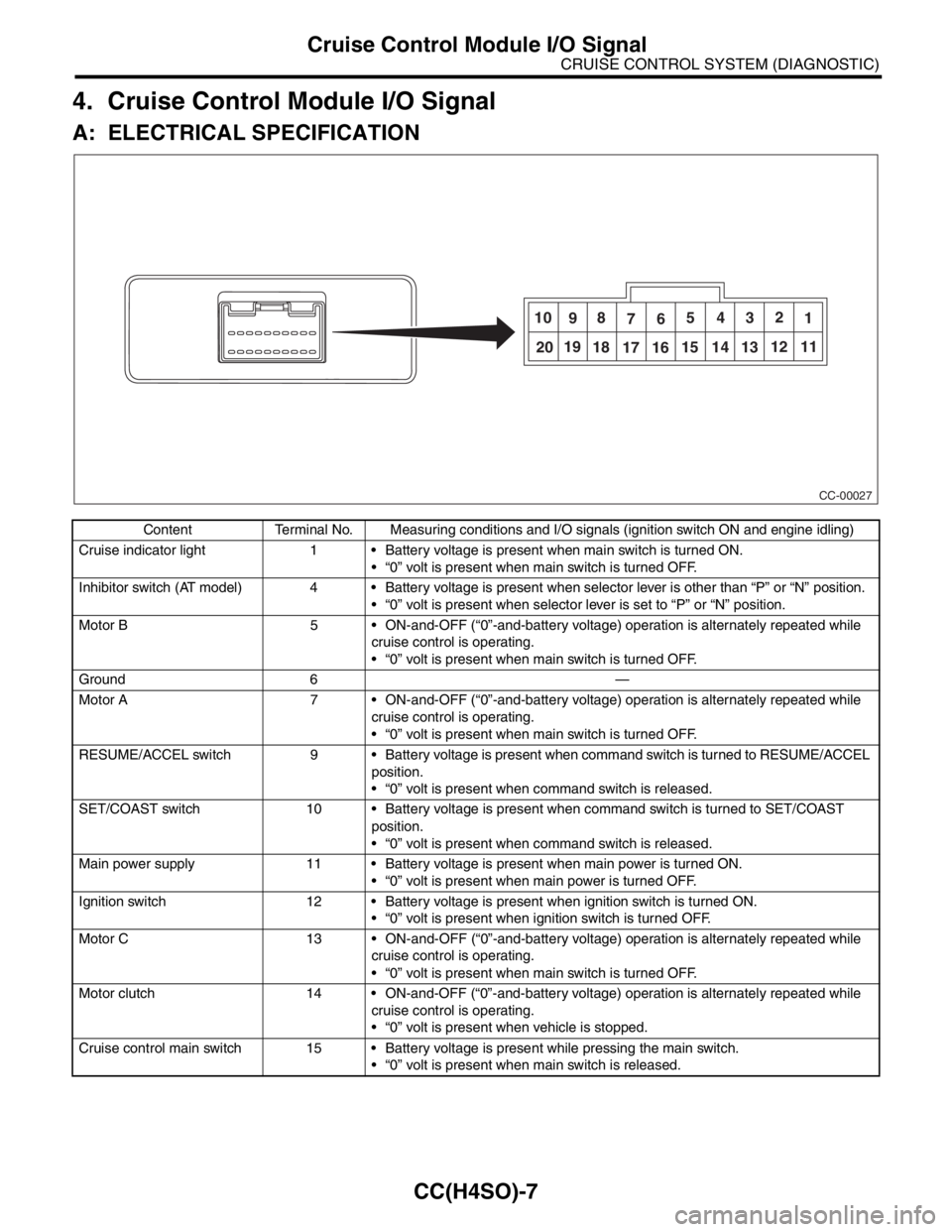
4. Cruise Control Module I/O Signal
A: ELECTRICAL SPECIFICATION
Content Terminal No. Measuring conditions and I/O signals (ignition switch ON and engine idling)
Cruise indicator light 1 Battery voltage is present when main switch is turned ON.
“0” volt is present when main switch is turned OFF.
Inhibitor switch (AT model) 4 Battery voltage is present when selector lever is other than “P” or “N” position.
“0” volt is present when selector lever is set to “P” or “N” position.
Motor B 5 ON-and-OFF (“0”-and-battery voltage) operation is alternately repeated while
cruise control is operating.
“0” volt is present when main switch is turned OFF.
Ground 6 —
Motor A 7 ON-and-OFF (“0”-and-battery voltage) operation is alternately repeated while
cruise control is operating.
“0” volt is present when main switch is turned OFF.
RESUME/ACCEL switch 9 Battery voltage is present when command switch is turned to RESUME/ACCEL
position.
“0” volt is present when command switch is released.
SET/COAST switch 10 Battery voltage is present when command switch is turned to SET/COAST
position.
“0” volt is present when command switch is released.
Main power supply 11 Battery voltage is present when main power is turned ON.
“0” volt is present when main power is turned OFF.
Ignition switch 12 Battery voltage is present when ignition switch is turned ON.
“0” volt is present when ignition switch is turned OFF.
Motor C 13 ON-and-OFF (“0”-and-battery voltage) operation is alternately repeated while
cruise control is operating.
“0” volt is present when main switch is turned OFF.
Motor clutch 14 ON-and-OFF (“0”-and-battery voltage) operation is alternately repeated while
cruise control is operating.
“0” volt is present when vehicle is stopped.
Cruise control main switch 15 Battery voltage is present while pressing the main switch.
“0” volt is present when main switch is released.
CC-00027
10
98
765432
1
2019
18
17 1615 14 1312 11
Page 576 of 2870

CC(H4SO)-8
CRUISE CONTROL SYSTEM (DIAGNOSTIC)
Cruise Control Module I/O Signal
B: WIRING DIAGRAM
Brake switch/Clutch switch
(MT model)16 Leave clutch pedal released (MT model), while cruise control main switch is
turned ON.
Then check that;
Battery voltage is present when brake pedal is released.
“0” volt is present when brake pedal is depressed.
Additionally only in MT model, keep the cruise control main switch to ON and
leave brake pedal released.
Then check that;
Battery voltage is present when clutch pedal is released.
“0” volt is present when clutch pedal is depressed.
Data link connector 17 —
Data link connector 18 —
Vehicle speed sensor (MT
model)
TCM (AT model)19 Lift-up the vehicle until all four wheels are raised off ground, and then rotate any
wheel manually.
Approx. “5” and “0” volt pulse signals are alternately input to cruise control mod-
ule.
Stop light switch 20 Turn ignition switch to OFF.
Then check that;
Battery voltage is present when brake pedal is depressed.
“0” volt is present when brake pedal is released.
NOTE:
Voltage at terminals 5, 7, 13 and 14 cannot be checked unless vehicle is driving by cruise control operation.Content Terminal No. Measuring conditions and I/O signals (ignition switch ON and engine idling)
Page 578 of 2870

CC(H4SO)-10
CRUISE CONTROL SYSTEM (DIAGNOSTIC)
Subaru Select Monitor
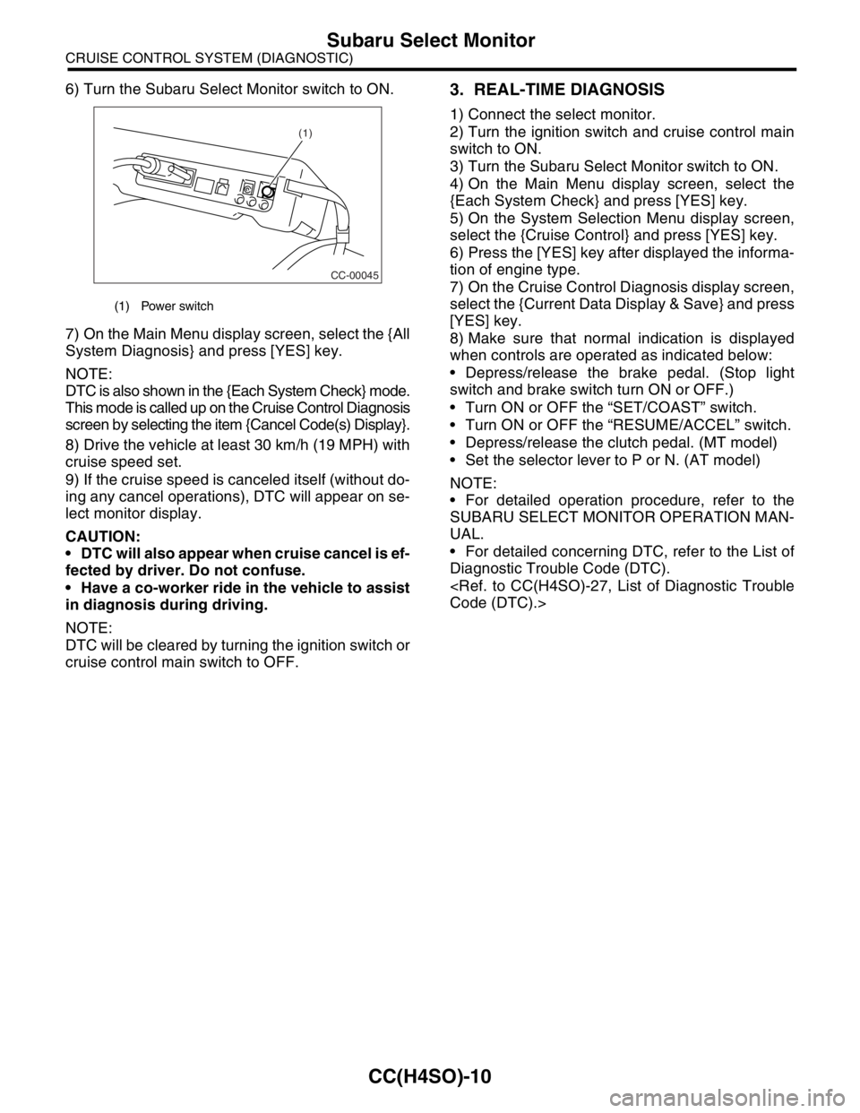
6) Turn the Subaru Select Monitor switch to ON.
7) On the Main Menu display screen, select the {All
System Diagnosis} and press [YES] key.
NOTE:
DTC is also shown in the {Each System Check} mode.
This mode is called up on the Cruise Control Diagnosis
screen by selecting the item {Cancel Code(s) Display}.
8) Drive the vehicle at least 30 km/h (19 MPH) with
cruise speed set.
9) If the cruise speed is canceled itself (without do-
ing any cancel operations), DTC will appear on se-
lect monitor display.
CAUTION:
DTC will also appear when cruise cancel is ef-
fected by driver. Do not confuse.
Have a co-worker ride in the vehicle to assist
in diagnosis during driving.
NOTE:
DTC will be cleared by turning the ignition switch or
cruise control main switch to OFF.3. REAL-TIME DIAGNOSIS
1) Connect the select monitor.
2) Turn the ignition switch and cruise control main
switch to ON.
3) Turn the Subaru Select Monitor switch to ON.
4) On the Main Menu display screen, select the
{Each System Check} and press [YES] key.
5) On the System Selection Menu display screen,
select the {Cruise Control} and press [YES] key.
6) Press the [YES] key after displayed the informa-
tion of engine type.
7) On the Cruise Control Diagnosis display screen,
select the {Current Data Display & Save} and press
[YES] key.
8) Make sure that normal indication is displayed
when controls are operated as indicated below:
Depress/release the brake pedal. (Stop light
switch and brake switch turn ON or OFF.)
Turn ON or OFF the “SET/COAST” switch.
Turn ON or OFF the “RESUME/ACCEL” switch.
Depress/release the clutch pedal. (MT model)
Set the selector lever to P or N. (AT model)
NOTE:
For detailed operation procedure, refer to the
SUBARU SELECT MONITOR OPERATION MAN-
UAL.
For detailed concerning DTC, refer to the List of
Diagnostic Trouble Code (DTC).
Code (DTC).>
(1) Power switch
CC-00045
(1)