2004 SUBARU FORESTER light
[x] Cancel search: lightPage 727 of 2870

PI-4
PRE-DELIVERY INSPECTION
Pre-delivery Inspection
Checks with the Engine Running
Dynamic Test with the Vehicle Running
Checks after Dynamic Test
Step Check point
26. Test mode connectors Test mode connectors
27. Starting condition Start the engine and check that the engine starts smoothly.
28. Exhaust system Check that the exhaust noise is normal and no leaks are found.
29. Indicator light Check that all the indicator lights operate normally.
30. Clock Check that the clock operates normally.
31. Radio Check that the radio system operates normally.
32. Front accessory power supply socket Check that the front accessory power supply socket operates normally.
33. Lighting system Check that the lighting systems operate normally.
34. Window washer Check that the window washer system operates normally.
35. Wiper Check that the wiper system operates normally.
36. Power window operation check Check the power window for correct operations.
Step Check point
37. Brake test Check that the foot brake operates normally.
38. Parking brake Check that the parking brake operates normally.
39. AT shift control Check the AT shift patterns are correct.
40. Heater & ventilation Check that the heater & ventilation system operates normally.
41. Air conditioner Check that the air conditioner operates normally.
42. Speed control Check that the speed control operates normally.
Step Check point
43. ATF level Check that the ATF level is normal.
44. Power steering fluid level Check that the power steering fluid level is normal.
45. Fluid leak check Check for fluid/oil leaks.
46. Water leak check Spray the vehicle with water and check for water leaks.
47. Appearance check 2 (1) Remove the protective coating (wrap guard).(if any)
(2) Check the body paints for damage and smears.
(3) Check the plated parts for damage and rust.
Page 728 of 2870
PI-5
PRE-DELIVERY INSPECTION
Pre-delivery Inspection
1. APPEARANCE CHECK
1) If the vehicle is covered with protective coating,
visually check the vehicle body for damage and
dents.
2) If there is no protective coating, check the body
paints for small areas of damage or stains and re-
pair as necessary.
3) Check the window glass, door glass, and lights
for any cracks or damage and repair or replace the
parts as necessary.
4) Check the plated parts, such as the grilles and
door knobs, for damage or loss of gloss and repair
or replace the parts as necessary.
2. TIRE CHECK
Check the tire outer faces for any damage.
Check the tire air pressure by referring to the fol-
lowing table.
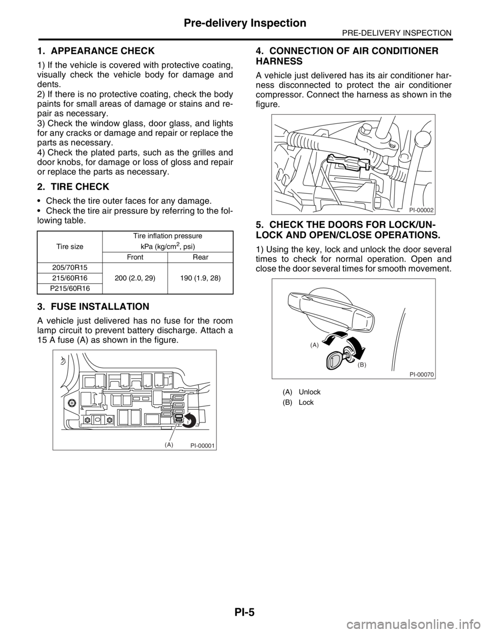
3. FUSE INSTALLATION
A vehicle just delivered has no fuse for the room
lamp circuit to prevent battery discharge. Attach a
15 A fuse (A) as shown in the figure.
4. CONNECTION OF AIR CONDITIONER
HARNESS
A vehicle just delivered has its air conditioner har-
ness disconnected to protect the air conditioner
compressor. Connect the harness as shown in the
figure.
5. CHECK THE DOORS FOR LOCK/UN-
LOCK AND OPEN/CLOSE OPERATIONS.
1) Using the key, lock and unlock the door several
times to check for normal operation. Open and
close the door several times for smooth movement.Tire sizeTire inflation pressure
kPa (kg/cm2, psi)
Front Rear
205/70R15
200 (2.0, 29) 190 (1.9, 28) 215/60R16
P215/60R16
PI-00001(A)
(A) Unlock
(B) Lock
PI-00002
PI-00070
(A)
(B)
Page 733 of 2870
PI-10
PRE-DELIVERY INSPECTION
Pre-delivery Inspection
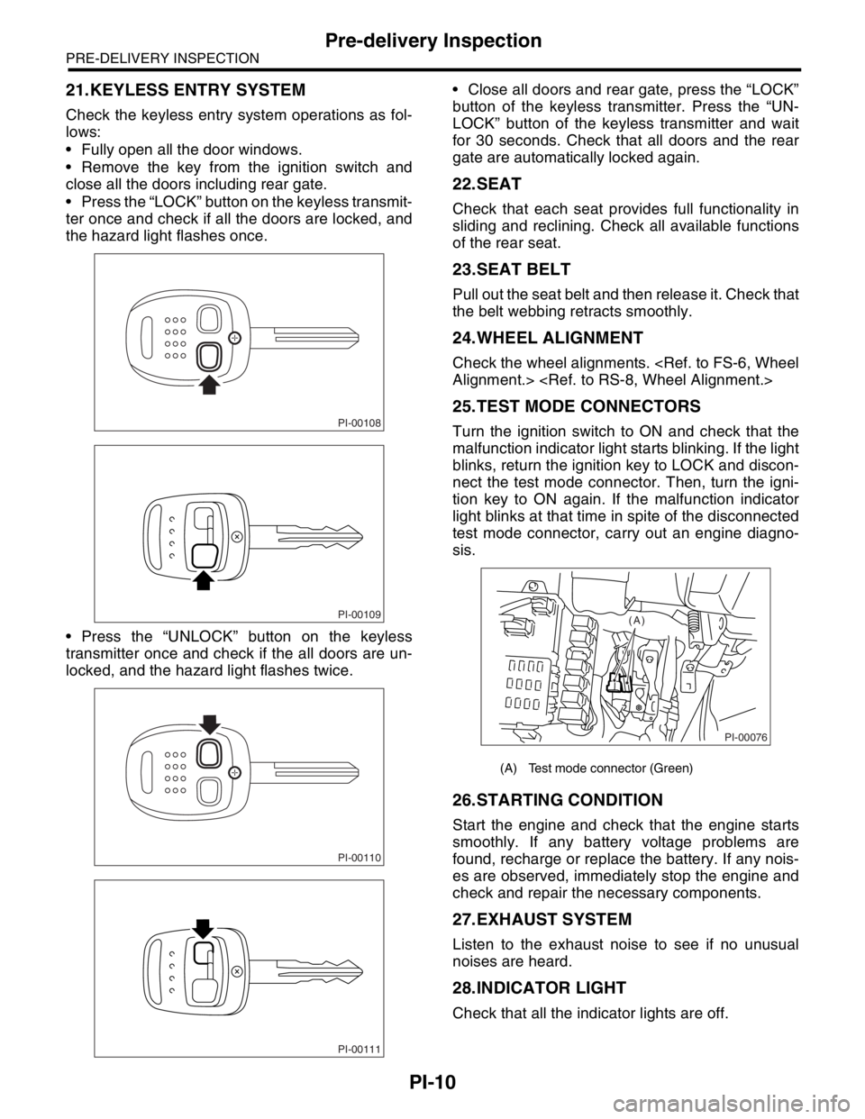
21.KEYLESS ENTRY SYSTEM
Check the keyless entry system operations as fol-
lows:
Fully open all the door windows.
Remove the key from the ignition switch and
close all the doors including rear gate.
Press the “LOCK” button on the keyless transmit-
ter once and check if all the doors are locked, and
the hazard light flashes once.
Press the “UNLOCK” button on the keyless
transmitter once and check if the all doors are un-
locked, and the hazard light flashes twice. Close all doors and rear gate, press the “LOCK”
button of the keyless transmitter. Press the “UN-
LOCK” button of the keyless transmitter and wait
for 30 seconds. Check that all doors and the rear
gate are automatically locked again.
22.SEAT
Check that each seat provides full functionality in
sliding and reclining. Check all available functions
of the rear seat.
23.SEAT BELT
Pull out the seat belt and then release it. Check that
the belt webbing retracts smoothly.
24.WHEEL ALIGNMENT
Check the wheel alignments.
25.TEST MODE CONNECTORS
Turn the ignition switch to ON and check that the
malfunction indicator light starts blinking. If the light
blinks, return the ignition key to LOCK and discon-
nect the test mode connector. Then, turn the igni-
tion key to ON again. If the malfunction indicator
light blinks at that time in spite of the disconnected
test mode connector, carry out an engine diagno-
sis.
26.STARTING CONDITION
Start the engine and check that the engine starts
smoothly. If any battery voltage problems are
found, recharge or replace the battery. If any nois-
es are observed, immediately stop the engine and
check and repair the necessary components.
27.EXHAUST SYSTEM
Listen to the exhaust noise to see if no unusual
noises are heard.
28.INDICATOR LIGHT
Check that all the indicator lights are off.
PI-00108
PI-00109
PI-00110
PI-00111
(A) Test mode connector (Green)
PI-00076
(A)
Page 734 of 2870
PI-11
PRE-DELIVERY INSPECTION
Pre-delivery Inspection
29.CLOCK
Check the clock for normal operations and enough
accuracy.
30.RADIO
Check the radio for full functionality and normal
noise level. Also check the CD unit operations.
31.FRONT ACCESSORY POWER SUPPLY
SOCKET
Check the front accessory power supply socket op-
erations.
32.LIGHTING SYSTEM
Check the headlight operations.
Check the brake light operations.
Check the other lights for normal operations.
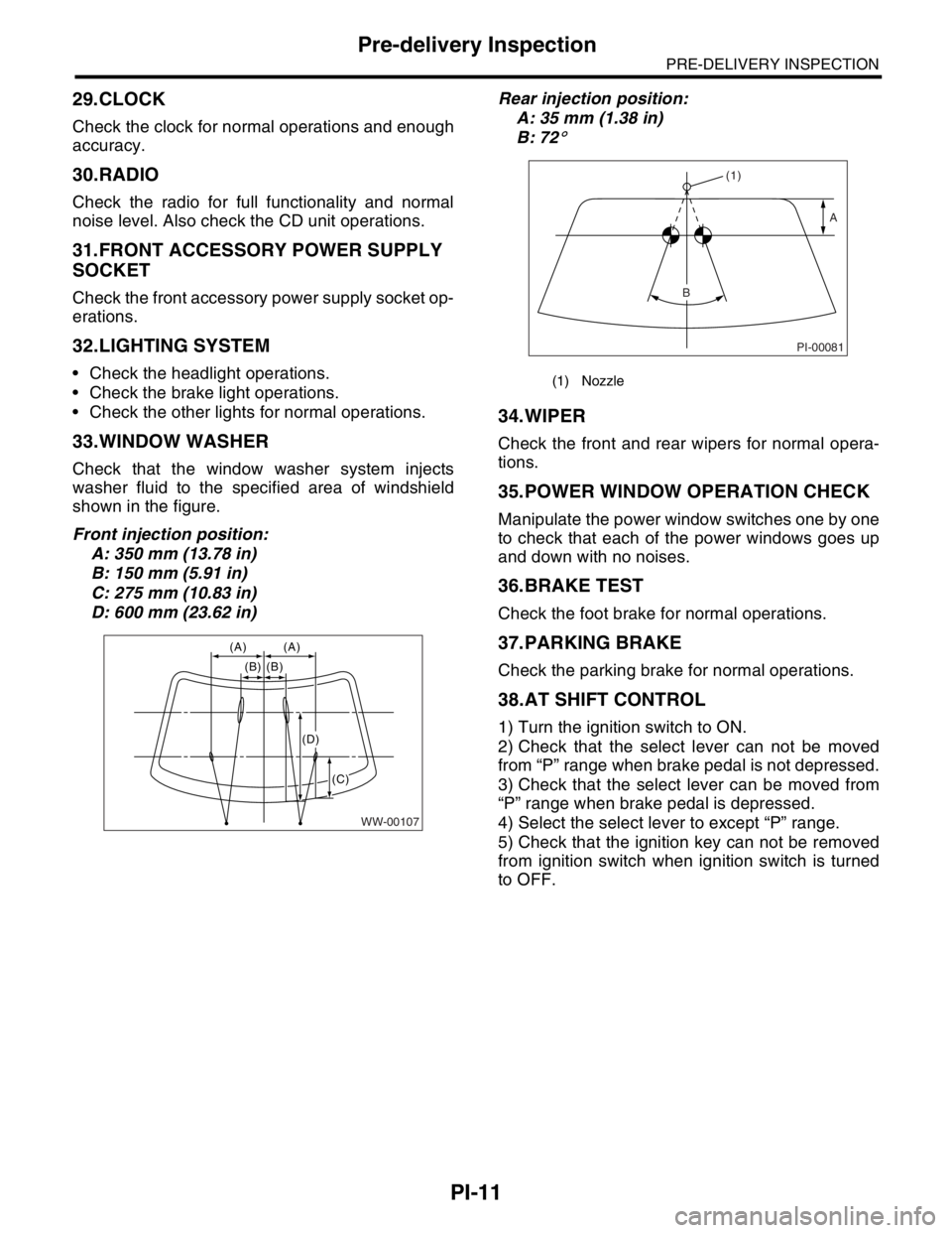
33.WINDOW WASHER
Check that the window washer system injects
washer fluid to the specified area of windshield
shown in the figure.
Front injection position:
A: 350 mm (13.78 in)
B: 150 mm (5.91 in)
C: 275 mm (10.83 in)
D: 600 mm (23.62 in)Rear injection position:
A: 35 mm (1.38 in)
B: 72
°
34.WIPER
Check the front and rear wipers for normal opera-
tions.
35.POWER WINDOW OPERATION CHECK
Manipulate the power window switches one by one
to check that each of the power windows goes up
and down with no noises.
36.BRAKE TEST
Check the foot brake for normal operations.
37.PARKING BRAKE
Check the parking brake for normal operations.
38.AT SHIFT CONTROL
1) Turn the ignition switch to ON.
2) Check that the select lever can not be moved
from “P” range when brake pedal is not depressed.
3) Check that the select lever can be moved from
“P” range when brake pedal is depressed.
4) Select the select lever to except “P” range.
5) Check that the ignition key can not be removed
from ignition switch when ignition switch is turned
to OFF.
WW-00107
(A) (A)
(B) (B)
(C)
(D)
(1) Nozzle
PI-00081
(1)
A
B
Page 736 of 2870

PI-13
PRE-DELIVERY INSPECTION
Pre-delivery Inspection
If any dampness in the compartment is discovered
after the water has been applied, carefully check all
areas that may have possibly contributed to the
leak.
45.APPEARANCE CHECK 2
1) When vehicle body is covered with protective
film (wrap guard), peel it off.
NOTE:
Use of steam eases peeling off the wrap guard.
When performing on the vehicles left for a long
time, or during low temperature period, sprinkle
some water heated to 50 — 60°C (122 — 140°F)
over the vehicle to raise its surface temperature be-
fore peeling off the wrap guard.
Do not use the water heated to over 60°C (140°F).
If the adhesive remains on the coated surface,
rub the portion with a flannel rag, etc. soaked with a
coat of coating wax or a solvent, such as oil ben-
zene and IPA, and then wipe it off.
Avoid adhesion of the solvent to resin or rubber
components. Do not use coating wax or a solvent
while the component surface temperature is high
due to hot weather, etc.
If the coated surface is swollen out due to seams
or moisture, expose the vehicle to the sun light for a
few hours. Otherwise, heat the portion with seams
or moisture using a dryer, etc.
Dispose of the peeled wrap guard as burnable in-
dustrial garbage.
2) Check the whole vehicle body for stains, flaking,
damage caused by transportation, rust, dirt, cracks,
or blistering.
NOTE:
It is better to determine an inspection pattern in
order to avoid missing an area, since the total in-
spection area is wide.
It is desirable not to make corrections to the body
paint unless absolutely needed. However, if any
corrections are required to remove scratches or
rust, the area to be corrected must be limited as
much as possible. Re-painting and spray painting
must be avoided whenever possible.
3) Carefully check each window glass for scratch-
es. Slight damage may be removed by polishing
with cerium oxide. (Half-fill a cup with cerium oxide,
and add warm water to it. Then agitate the content
until it turn to wax. Apply this wax to a soft cloth,
and polish the glass.)4) Check each portion of the vehicle body and un-
derside components for the formation of rust. If rust
is discovered, remove it with #80 — #180 emery
paper, and treat the surface with rust preventive.
After this treatment is completed, flush the portion
thoroughly, and prepare the surface for repair
painting.
5) Check each portion of the body and all of the
chrome parts for deformation or distortion. Also
check each lamp lens for cracks.
Page 747 of 2870
PM-10
PERIODIC MAINTENANCE SERVICE
Spark Plugs
5. Spark Plugs
A: REPLACEMENT
1) Remove the intake duct and intake chamber.
2) Remove the washer tank and put it aside.
3) Disconnect the spark plug cord.
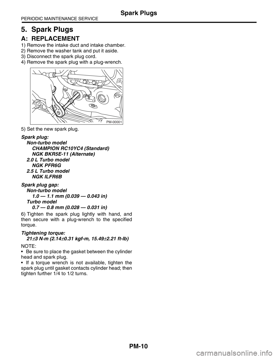
4) Remove the spark plug with a plug-wrench.
5) Set the new spark plug.
Spark plug:
Non-turbo model
CHAMPION RC10YC4 (Standard)
NGK BKR5E-11 (Alternate)
2.0 L Turbo model
NGK PFR6G
2.5 L Turbo model
NGK ILFR6B
Spark plug gap:
Non-turbo model
1.0 — 1.1 mm (0.039 — 0.043 in)
Turbo model
0.7 — 0.8 mm (0.028 — 0.031 in)
6) Tighten the spark plug lightly with hand, and
then secure with a plug-wrench to the specified
torque.
Tightening torque:
21
±3 N·m (2.14±0.31 kgf-m, 15.49±2.21 ft-lb)
NOTE:
Be sure to place the gasket between the cylinder
head and spark plug.
If a torque wrench is not available, tighten the
spark plug until gasket contacts cylinder head; then
tighten further 1/4 to 1/2 turns.
PM-00001
Page 762 of 2870
PM-25
PERIODIC MAINTENANCE SERVICE
Hill-holder System
15.Hill-holder System
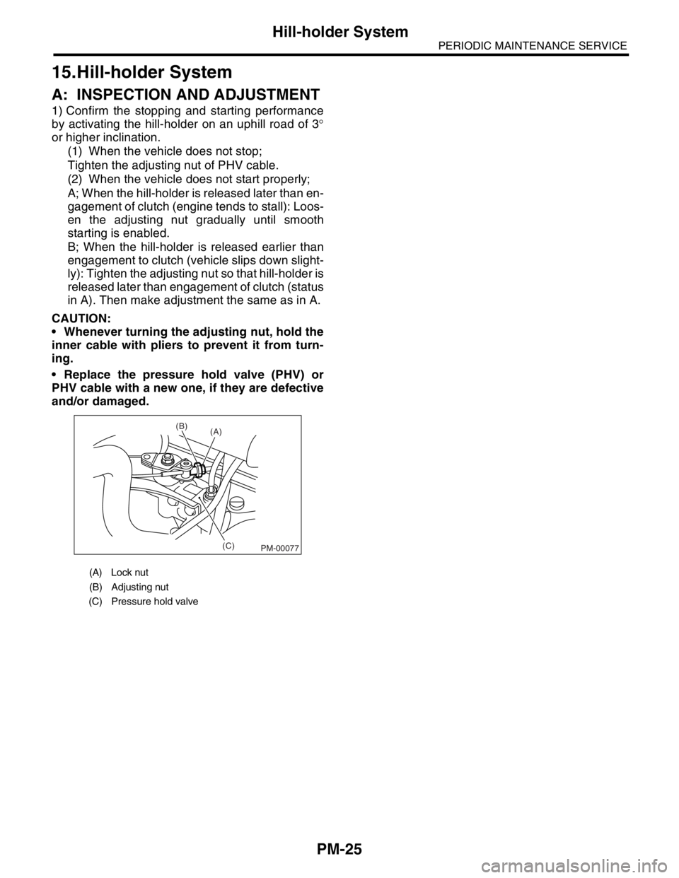
A: INSPECTION AND ADJUSTMENT
1) Confirm the stopping and starting performance
by activating the hill-holder on an uphill road of 3°
or higher inclination.
(1) When the vehicle does not stop;
Tighten the adjusting nut of PHV cable.
(2) When the vehicle does not start properly;
A; When the hill-holder is released later than en-
gagement of clutch (engine tends to stall): Loos-
en the adjusting nut gradually until smooth
starting is enabled.
B; When the hill-holder is released earlier than
engagement to clutch (vehicle slips down slight-
ly): Tighten the adjusting nut so that hill-holder is
released later than engagement of clutch (status
in A). Then make adjustment the same as in A.
CAUTION:
Whenever turning the adjusting nut, hold the
inner cable with pliers to prevent it from turn-
ing.
Replace the pressure hold valve (PHV) or
PHV cable with a new one, if they are defective
and/or damaged.
(A) Lock nut
(B) Adjusting nut
(C) Pressure hold valve
(C) (B)
(A)
PM-00077
Page 767 of 2870
PM-30
PERIODIC MAINTENANCE SERVICE
Brake Line
18.Brake Line
A: INSPECTION
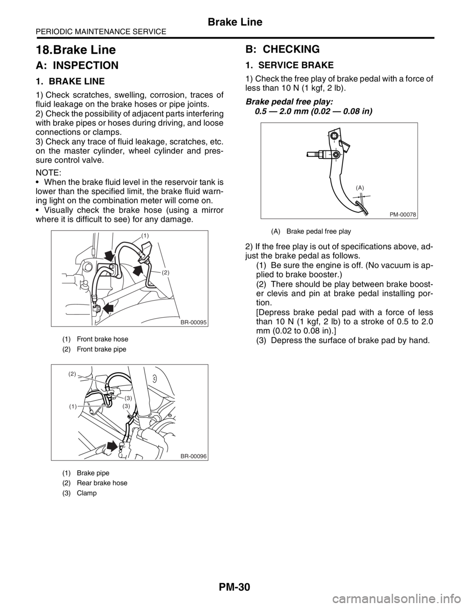
1. BRAKE LINE
1) Check scratches, swelling, corrosion, traces of
fluid leakage on the brake hoses or pipe joints.
2) Check the possibility of adjacent parts interfering
with brake pipes or hoses during driving, and loose
connections or clamps.
3) Check any trace of fluid leakage, scratches, etc.
on the master cylinder, wheel cylinder and pres-
sure control valve.
NOTE:
When the brake fluid level in the reservoir tank is
lower than the specified limit, the brake fluid warn-
ing light on the combination meter will come on.
Visually check the brake hose (using a mirror
where it is difficult to see) for any damage.
B: CHECKING
1. SERVICE BRAKE
1) Check the free play of brake pedal with a force of
less than 10 N (1 kgf, 2 lb).
Brake pedal free play:
0.5 — 2.0 mm (0.02 — 0.08 in)
2) If the free play is out of specifications above, ad-
just the brake pedal as follows.
(1) Be sure the engine is off. (No vacuum is ap-
plied to brake booster.)
(2) There should be play between brake boost-
er clevis and pin at brake pedal installing por-
tion.
[Depress brake pedal pad with a force of less
than 10 N (1 kgf, 2 lb) to a stroke of 0.5 to 2.0
mm (0.02 to 0.08 in).]
(3) Depress the surface of brake pad by hand.
(1) Front brake hose
(2) Front brake pipe
(1) Brake pipe
(2) Rear brake hose
(3) Clamp
BR-00095
(1)
(2)
(1)
(3)
(3) (2)
BR-00096
(A) Brake pedal free play
PM-00078
(A)