Page 1059 of 2870
SP(H4SO)-6
SPEED CONTROL SYSTEM
Accelerator Pedal
C: DISASSEMBLY
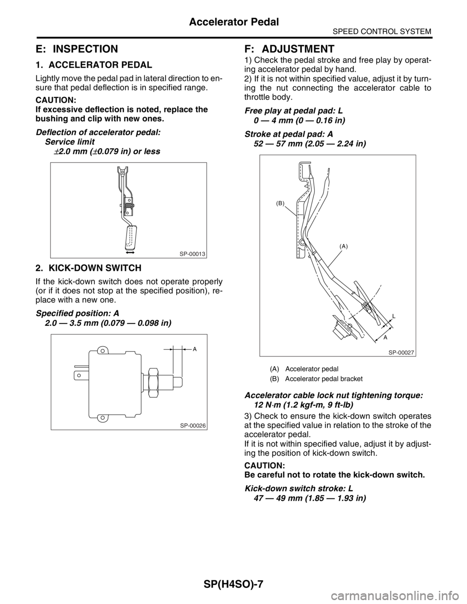
1) Remove the clip, and then remove the accelera-
tor pedal lever from accelerator bracket.
2) Pull out the spring pin, and then remove the ac-
celerator pedal from accelerator pedal lever.
LHD model RHD model
D: ASSEMBLY
Assemble in the reverse order of disassembly.
NOTE:
Clean and apply grease to the portions indicated in
the figure.
Grease:
SUNLIGHT No. 2 (Part No. 003602010)
(A) Accelerator bracket
(B) Stopper
(C) Bushing
(D) Clip
(E) Accelerator spring
(F) Accelerator pedal spring
(G) Accelerator pedal lever
(H) Spring pin
(I) Accelerator pedal
(J) Kick-down switch (AT model)
SP-00024
(H) (A)
(B)
(C)
(D)
(F)(J) (E)
(I) (G)
(A) Accelerator bracket
(B) Stopper
(C) Bushing
(D) Clip
(E) Accelerator spring
(F) Accelerator pedal spring
(G) Accelerator pedal lever
(H) Spring pin
(I) Accelerator pedal
(J) Kick-down switch (AT model)
SP-00025
(A)
(B)(G)
(J)
(C)
(E) (D)
(H)(F)
(I)
Page 1060 of 2870

SP(H4SO)-7
SPEED CONTROL SYSTEM
Accelerator Pedal
E: INSPECTION
1. ACCELERATOR PEDAL
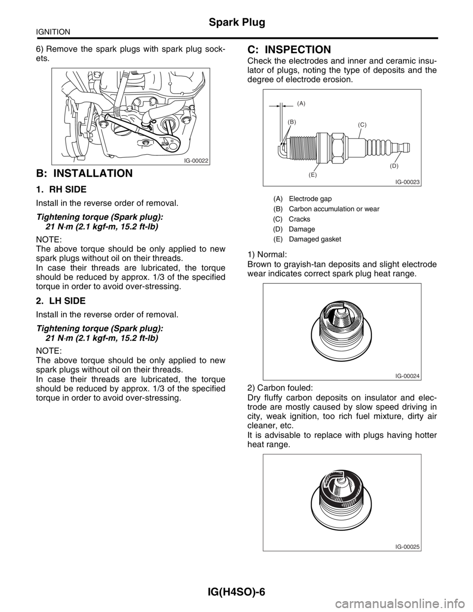
Lightly move the pedal pad in lateral direction to en-
sure that pedal deflection is in specified range.
CAUTION:
If excessive deflection is noted, replace the
bushing and clip with new ones.
Deflection of accelerator pedal:
Service limit
±2.0 mm (±0.079 in) or less
2. KICK-DOWN SWITCH
If the kick-down switch does not operate properly
(or if it does not stop at the specified position), re-
place with a new one.
Specified position: A
2.0 — 3.5 mm (0.079 — 0.098 in)
F: ADJUSTMENT
1) Check the pedal stroke and free play by operat-
ing accelerator pedal by hand.
2) If it is not within specified value, adjust it by turn-
ing the nut connecting the accelerator cable to
throttle body.
Free play at pedal pad: L
0 — 4 mm (0 — 0.16 in)
Stroke at pedal pad: A
52 — 57 mm (2.05 — 2.24 in)
Accelerator cable lock nut tightening torque:
12 N
⋅m (1.2 kgf-m, 9 ft-lb)
3) Check to ensure the kick-down switch operates
at the specified value in relation to the stroke of the
accelerator pedal.
If it is not within specified value, adjust it by adjust-
ing the position of kick-down switch.
CAUTION:
Be careful not to rotate the kick-down switch.
Kick-down switch stroke: L
47 — 49 mm (1.85 — 1.93 in)
SP-00013
SP-00026
A
(A) Accelerator pedal
(B) Accelerator pedal bracket
SP-00027
(A)
L
A (B)
Page 1070 of 2870

IG(H4SO)-6
IGNITION
Spark Plug
6) Remove the spark plugs with spark plug sock-
ets.
B: INSTALLATION
1. RH SIDE
Install in the reverse order of removal.
Tightening torque (Spark plug):
21 N
⋅m (2.1 kgf-m, 15.2 ft-lb)
NOTE:
The above torque should be only applied to new
spark plugs without oil on their threads.
In case their threads are lubricated, the torque
should be reduced by approx. 1/3 of the specified
torque in order to avoid over-stressing.
2. LH SIDE
Install in the reverse order of removal.
Tightening torque (Spark plug):
21 N
⋅m (2.1 kgf-m, 15.2 ft-lb)
NOTE:
The above torque should be only applied to new
spark plugs without oil on their threads.
In case their threads are lubricated, the torque
should be reduced by approx. 1/3 of the specified
torque in order to avoid over-stressing.
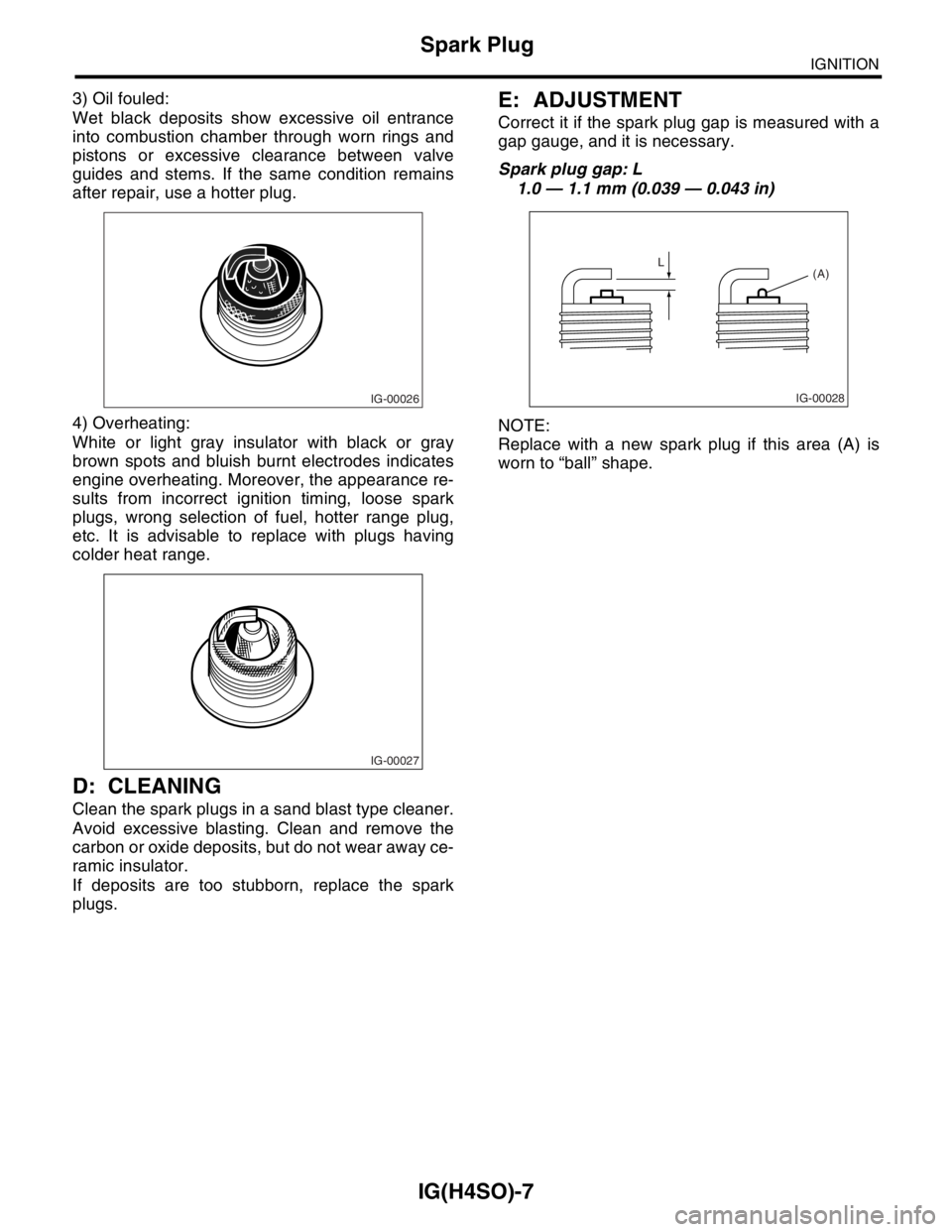
C: INSPECTION
Check the electrodes and inner and ceramic insu-
lator of plugs, noting the type of deposits and the
degree of electrode erosion.
1) Normal:
Brown to grayish-tan deposits and slight electrode
wear indicates correct spark plug heat range.
2) Carbon fouled:
Dry fluffy carbon deposits on insulator and elec-
trode are mostly caused by slow speed driving in
city, weak ignition, too rich fuel mixture, dirty air
cleaner, etc.
It is advisable to replace with plugs having hotter
heat range.
IG-00022
(A) Electrode gap
(B) Carbon accumulation or wear
(C) Cracks
(D) Damage
(E) Damaged gasket
IG-00023
(A)
(B)
(C)
(D)
(E)
IG-00024
IG-00025
Page 1071 of 2870

IG(H4SO)-7
IGNITION
Spark Plug
3) Oil fouled:
Wet black deposits show excessive oil entrance
into combustion chamber through worn rings and
pistons or excessive clearance between valve
guides and stems. If the same condition remains
after repair, use a hotter plug.
4) Overheating:
White or light gray insulator with black or gray
brown spots and bluish burnt electrodes indicates
engine overheating. Moreover, the appearance re-
sults from incorrect ignition timing, loose spark
plugs, wrong selection of fuel, hotter range plug,
etc. It is advisable to replace with plugs having
colder heat range.
D: CLEANING
Clean the spark plugs in a sand blast type cleaner.
Avoid excessive blasting. Clean and remove the
carbon or oxide deposits, but do not wear away ce-
ramic insulator.
If deposits are too stubborn, replace the spark
plugs.
E: ADJUSTMENT
Correct it if the spark plug gap is measured with a
gap gauge, and it is necessary.
Spark plug gap: L
1.0 — 1.1 mm (0.039 — 0.043 in)
NOTE:
Replace with a new spark plug if this area (A) is
worn to “ball” shape.
IG-00026
IG-00027
IG-00028
L
(A)
Page 1083 of 2870
SC(H4SO)-8
STARTING/CHARGING SYSTEM
Starter
7) Remove the plate.
8) Remove the shaft assembly and overrunning
clutch from front bracket as a unit.
NOTE:
Check the following points before removal.
Lever direction
Position of internal gear assembly
9) Remove the overrunning clutch from shaft as-
sembly as follows:
(1) Remove the stopper from ring by lightly tap-
ping the stopper with an appropriate tool (such
as a 14 mm (0.55 in) a fit socket wrench).(2) Remove the ring, stopper and clutch from
shaft.
(A) Plate
(A) Lever
(B) Shaft ASSY
(C) Overrunning clutch
(D) Internal gear ASSY
SC-00065
(A)
SC-00066
(A)
(D)
(C) (B)
(A) Socket wrench
(B) Ring
(C) Shaft
(D) Stopper
SC-00014
Page 1084 of 2870
SC(H4SO)-9
STARTING/CHARGING SYSTEM
Starter
D: ASSEMBLY
NOTE:
Apply grease to the following parts before assem-
bly.
Sleeve bearing
Pinion shaft rotational portion
Shaft spline portion
Inside of reduction system
Lever fulcrum/Clutch rotational portion
1) Install the overrunning clutch to shaft assembly.
2) Install the stopper to shaft assembly as follows.
(1) Insert the ring into the shaft groove by lightly
tapping it with an appropriate tool (such as a fit
socket wrench).
(2) Install the stopper to ring using a press.
3) Install the shaft assembly to front bracket while
taking care of the following points.
(1) Lever direction(2) Internal gear position
4) Install the plate.
5) Install the planetary gear.
6) Install packing A and B while taking care of in-
stalling positions.
7) Install the armature to yoke assembly.
(A) Ring
(B) Stopper
SC-00067
(B)(A)
SC-00068
(A)
(B)
SC-00069
(A) Plate
(A) Packing A
(B) Packing B
SC-00070
SC-00065
(A)
SC-00071
(A)
(B)
Page 1099 of 2870

ENGINE (DIAGNOSTIC)
EN(H4SO)
Page
1. Basic Diagnostics Procedure ......................................................................2
2. Check List for Interview ...............................................................................4
3. General Description ....................................................................................6
4. Electrical Component Location ...................................................................9
5. Engine Control Module (ECM) I/O Signal .................................................21
6. Engine Condition Data ..............................................................................24
7. Transmission Control Module (TCM) I/O Signal .......................................25
8. Data Link Connector .................................................................................26
9. OBD-II General Scan Tool ........................................................................27
10. Subaru Select Monitor...............................................................................29
11. Read Diagnostic Trouble Code (DTC) ......................................................36
12. Inspection Mode ........................................................................................37
13. Drive Cycle ................................................................................................42
14. Clear Memory Mode..................................................................................44
15. Compulsory Valve Operation Check Mode ...............................................45
16. Malfunction Indicator Light ........................................................................47
17. Diagnostics for Engine Starting Failure .....................................................57
18. List of Diagnostic Trouble Code (DTC) .....................................................72
19. Diagnostic Procedure with Diagnostic Trouble Code (DTC) .....................78
20. General Diagnostic Table........................................................................255
Page 1100 of 2870

EN(H4SO)-2
ENGINE (DIAGNOSTIC)
Basic Diagnostics Procedure
1. Basic Diagnostics Procedure
A: PROCEDURE
1. ENGINE
Step Check Yes No
1 CHECK ENGINE START FAILURE.
1) Ask the customer when and how the trou-
ble occurred using the interview check list.
List for Interview.>
2) Start the engine.Does the engine start? Go to step 2.Inspection using
“Diagnostics for
Engine Starting
Failure”.
EN(H4SO)-57,
Diagnostics for
Engine Starting
Fai lu r e.>
2 CHECK ILLUMINATION OF MALFUNCTION
INDICATOR LIGHT.Does malfunction indicator
light illuminate?Go to step 3.Inspection using
“General Diagnos-
tic Table”.
EN(H4SO)-255,
INSPECTION,
General Diagnos-
tic Table.>
3 CHECK INDICATION OF DTC ON DISPLAY
1) Turn the ignition switch to OFF.
2) Connect the Subaru Select Monitor or the
OBD-II general scan tool to data link connec-
tor.
3) Turn the ignition switch to ON and the Sub-
aru Select Monitor or OBD-II general scan tool
switch to ON.
4) Read the DTC on the Subaru Select Moni-
tor or OBD-II general scan tool.Does the Subaru Select Moni-
tor or OBD-II general scan tool
indicate DTC?Record the DTC.
Repair the trouble
cause.
EN(H4SO)-72, List
of Diagnostic Trou-
ble Code (DTC).>
Go to step 4.Repair the related
parts.
N
OTE:
If DTC is not shown
on display although
the engine warning
light illuminates, per-
form the diagnostics
of engine warning
light circuit or combi-
nation meter.
to EN(H4SO)-47,
Malfunction Indica-
tor Light.>
4 PERFORM THE DIAGNOSIS.
1) Perform the Clear Memory Mode.
EN(H4SO)-44, Clear Memory Mode.>
2) Perform the Inspection Mode.
EN(H4SO)-37, Inspection Mode.>Does the Subaru Select Moni-
tor or OBD-II general scan tool
indicate DTC?Check on “Diag-
nostic Procedure
with Diagnostic
Trouble Code
(DTC)”
EN(H4SO)-78,
Diagnostic Proce-
dure with Diagnos-
tic Trouble Code
(DTC).>Finish the diagno-
sis.