2004 SUBARU FORESTER light
[x] Cancel search: lightPage 1125 of 2870

EN(H4SO)-27
ENGINE (DIAGNOSTIC)
OBD-II General Scan Tool
9. OBD-II General Scan Tool
A: OPERATION
1. HOW TO USE OBD-II GENERAL SCAN
TOOL
1) Prepare a general scan tool (OBD-II general
scan tool) required by SAE J1978.
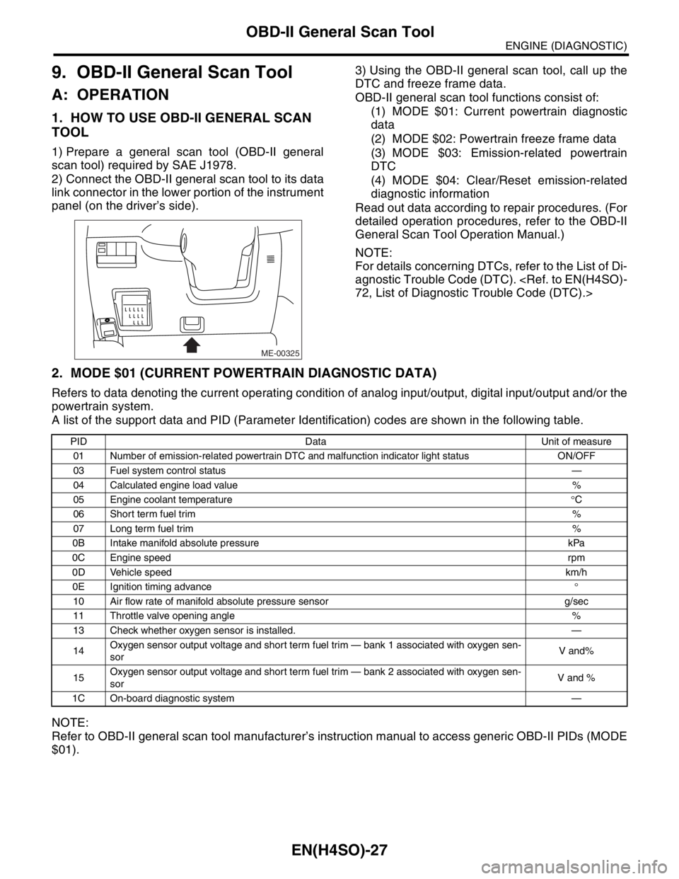
2) Connect the OBD-II general scan tool to its data
link connector in the lower portion of the instrument
panel (on the driver’s side).3) Using the OBD-II general scan tool, call up the
DTC and freeze frame data.
OBD-II general scan tool functions consist of:
(1) MODE $01: Current powertrain diagnostic
data
(2) MODE $02: Powertrain freeze frame data
(3) MODE $03: Emission-related powertrain
DTC
(4) MODE $04: Clear/Reset emission-related
diagnostic information
Read out data according to repair procedures. (For
detailed operation procedures, refer to the OBD-II
General Scan Tool Operation Manual.)
NOTE:
For details concerning DTCs, refer to the List of Di-
agnostic Trouble Code (DTC).
2. MODE $01 (CURRENT POWERTRAIN DIAGNOSTIC DATA)
Refers to data denoting the current operating condition of analog input/output, digital input/output and/or the
powertrain system.
A list of the support data and PID (Parameter Identification) codes are shown in the following table.
NOTE:
Refer to OBD-II general scan tool manufacturer’s instruction manual to access generic OBD-II PIDs (MODE
$01).
ME-00325
PID Data Unit of measure
01 Number of emission-related powertrain DTC and malfunction indicator light status ON/OFF
03 Fuel system control status—
04 Calculated engine load value%
05 Engine coolant temperature°C
06 Short term fuel trim%
07 Long term fuel trim%
0B Intake manifold absolute pressure kPa
0C Engine speedrpm
0D Vehicle speedkm/h
0E Ignition timing advance°
10 Air flow rate of manifold absolute pressure sensor g/sec
11 Throttle valve opening angle%
13 Check whether oxygen sensor is installed. —
14Oxygen sensor output voltage and short term fuel trim — bank 1 associated with oxygen sen-
sorV and%
15Oxygen sensor output voltage and short term fuel trim — bank 2 associated with oxygen sen-
sorV and %
1C On-board diagnostic system—
Page 1129 of 2870

EN(H4SO)-31
ENGINE (DIAGNOSTIC)
Subaru Select Monitor
NOTE:
For detailed operation procedure, refer to the “SUBARU SELECT MONITOR OPERATION MANUAL”.
Engine torque control permission signalAT coordinate permission sig-
nalON or OFF
Rear oxygen sensor rich signal Rear O2 monitor ON or OFF
Starter switch signal Starter SW ON or OFF
Idle switch signal Soft idle SW ON or OFF
Crankshaft position sensor signal Crankshaft position signal ON or OFF
Camshaft position sensor signal Camshaft position signal ON or OFF
Rear defogger switch signal Rear defogger SW ON or OFF
Blower fan switch signal Blower fan SW ON or OFF
Small light switch signal Light SW ON or OFF
AT vehicle ID signal AT/MT identification terminal AT or MT
A/C middle pressure switch signal A/C middle pressure SW ON or OFFDescription Display Unit of measure
Page 1130 of 2870
![SUBARU FORESTER 2004 Service Repair Manual EN(H4SO)-32
ENGINE (DIAGNOSTIC)
Subaru Select Monitor
5. READ CURRENT DATA FOR ENGINE (OBD MODE)
1) On the «Main Menu» display screen, select the {Each System Check} and press the [YES] key.
2) On t SUBARU FORESTER 2004 Service Repair Manual EN(H4SO)-32
ENGINE (DIAGNOSTIC)
Subaru Select Monitor
5. READ CURRENT DATA FOR ENGINE (OBD MODE)
1) On the «Main Menu» display screen, select the {Each System Check} and press the [YES] key.
2) On t](/manual-img/17/57426/w960_57426-1129.png)
EN(H4SO)-32
ENGINE (DIAGNOSTIC)
Subaru Select Monitor
5. READ CURRENT DATA FOR ENGINE (OBD MODE)
1) On the «Main Menu» display screen, select the {Each System Check} and press the [YES] key.
2) On the «System Selection Menu» display screen, select the {Engine} and press the [YES] key.
3) Press the [YES] key after the information of engine type was displayed.
4) On the «Engine Diagnosis» display screen, select the {OBD system} and press the [YES] key.
5) On the «OBD Menu» display screen, select the {Current Data Display & Save}, and press the [YES] key.
6) On the «Data Display Menu» display screen, select the {Data Display} and press the [YES] key.
7) Using the scroll key, scroll the display screen up or down until the desired data is shown.
A list of the support data is shown in the following table.
NOTE:
For detailed operation procedure, refer to the “SUBARU SELECT MONITOR OPERATION MANUAL”.
Description Display Unit of measure
Number of DTC Number of diagnosis code —
Condition of malfunction indicator light MI (MIL) ON or OFF
Monitoring test of misfire Misfire Monitoring Complete or incomplete
Monitoring test of fuel system Fuel System Diagnosis Complete or incomplete
Monitoring test of comprehensive component Component Diagnosis Complete or incomplete
Test of catalyst Catalyst diagnosis Complete or incomplete
Test of heating-type catalyst Heated catalyst diagnosis No support
Test of evaporative emission purge control system Evap. purge diagnosis Complete or incomplete
Test of secondary air system Secondary air diagnosis No support
Test of air conditioning system refrigerant A/C refrigerant diagnosis No support
Test of oxygen sensor O2 sensor diagnosis Complete or incomplete
Test of oxygen sensor heater O2 heater diagnosis Complete or incomplete
Test of EGR system EGR diagnosis —
Air fuel ratio control system for bank 1 Fuel System for bank 1 —
Engine load data Engine load %
Engine coolant temperature signal Engine coolant temperature°C or (°F)
Short term fuel trim by front oxygen (A/F) sensor Short term fuel trim B1 %
Long term fuel trim by front oxygen (A/F) sensor Long term fuel trim B1 %
Intake manifold absolute pressure signalIntake manifold absolute pres-
suremmHg, kPa, inHg or psi
Engine speed signal Engine speed rpm
Vehicle speed signal Meter vehicle speed km/h or MPH
Ignition timing advance for #1 cylinder Ignition timing adv. #1°
Intake air temperature signal Intake air temperature°C or (°F)
Amount of intake air Amount of intake air g/s
Throttle position signal Throttle valve angle %
Rear oxygen sensor output signal O2 sensor #12 V
Air fuel ratio correction by rear oxygen sensor Short term fuel trim #12 %
On-board diagnostic system OBD system —
Oxygen sensor #11 O2 sensor #11 With support
Oxygen sensor #12 O2 sensor #12 With support
A/F sensor #11 A/F sensor #11 —
Page 1133 of 2870
![SUBARU FORESTER 2004 Service Repair Manual EN(H4SO)-35
ENGINE (DIAGNOSTIC)
Subaru Select Monitor
8. READ CURRENT DATA FOR AT
1) On the «Main Menu» display screen, select the {Each System Check} and press the [YES] key.
2) On the «System Sel SUBARU FORESTER 2004 Service Repair Manual EN(H4SO)-35
ENGINE (DIAGNOSTIC)
Subaru Select Monitor
8. READ CURRENT DATA FOR AT
1) On the «Main Menu» display screen, select the {Each System Check} and press the [YES] key.
2) On the «System Sel](/manual-img/17/57426/w960_57426-1132.png)
EN(H4SO)-35
ENGINE (DIAGNOSTIC)
Subaru Select Monitor
8. READ CURRENT DATA FOR AT
1) On the «Main Menu» display screen, select the {Each System Check} and press the [YES] key.
2) On the «System Selection Menu» display screen, select the {Transmission} and press the [YES] key.
3) Press the [YES] key after the information of transmission type is displayed.
4) On the «Transmission Diagnosis» display screen, select the {Current Data Display & Save} and press the
[YES] key.
5) On the «Transmission Diagnosis» display screen, select the {Data Display} and press the [YES] key.
6) Using the scroll key, scroll the display screen up or down until the desired data is shown.
A list of the support data is shown in the following table.
Description Display Unit of measure
Battery voltage Battery Voltage V
Rear vehicle speed sensor signal Rear Wheel Speed km/h or MPH
Front vehicle speed sensor signal Front Wheel Speed km/h or MPH
Engine speed signal Engine speed rpm
ATF temperature signal ATF Temp.°C or °F
Throttle position sensor Throttle Sensor Voltage V
Gear Position Gear position —
Line pressure control duty ratio Line pressure duty %
Lock up clutch control duty ratio L/U Duty %
Transfer clutch control duty ratio AWD duty %
Throttle position sensor power supply Throttle sensor power supply V
Turbine revolution signal Turbine Revolution Speed rpm
2-4 Brake timing pressure control duty ratio 2-4 B Pressure Duty %
Intake manifold pressure sensor voltage Mani. Relative Voltage V
FWD switch signal FWD SW ON or OFF
Kick down switch signal Kick Down Switch ON or OFF
Stop light switch signal Stop Light SW ON or OFF
Anti lock brake system signal ABS signal ON or OFF
Cruise control system signal Cruise Control Signal ON or OFF
Neutral/Parking range signal N/P range ON or OFF
Reverse range signal R Range ON or OFF
Drive range signal D Range ON or OFF
3rd range signal 3rd Range Signal ON or OFF
2nd range signal 2nd Range Signal ON or OFF
1st range signal 1st Range Signal ON or OFF
Shift control solenoid A Shift Solenoid #1 ON or OFF
Shift control solenoid B Shift Solenoid #2 ON or OFF
Torque control output signal #1 Torque control output signal 1 ON or OFF
Torque control output signal #2 Torque control output signal 2 ON or OFF
Torque control cut signal Torque Control Cut Sig ON or OFF
2-4 brake timing control solenoid valve 2-4B Timing Solenoid ON or OFF
Low clutch timing control solenoid valve L/C timing solenoid ON or OFF
Automatic transmission diagnosis light output signal Diagnosis Lamp ON or OFF
Page 1138 of 2870

EN(H4SO)-40
ENGINE (DIAGNOSTIC)
Inspection Mode
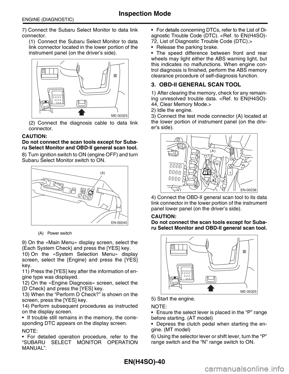
7) Connect the Subaru Select Monitor to data link
connector.
(1) Connect the Subaru Select Monitor to data
link connector located in the lower portion of the
instrument panel (on the driver’s side).
(2) Connect the diagnosis cable to data link
connector.
CAUTION:
Do not connect the scan tools except for Suba-
ru Select Monitor and OBD-II general scan tool.
8) Turn ignition switch to ON (engine OFF) and turn
Subaru Select Monitor switch to ON.
9) On the «Main Menu» display screen, select the
{Each System Check} and press the [YES] key.
10) On the «System Selection Menu» display
screen, select the {Engine} and press the [YES]
key.
11) Press the [YES] key after the information of en-
gine type was displayed.
12) On the «Engine Diagnosis» screen, select the
{D Check} and press the [YES] key.
13) When the “Perform D Check?” is shown on the
screen, press the [YES] key.
14) Perform subsequent procedures as instructed
on the display screen.
If trouble still remains in the memory, the corre-
sponding DTC appears on the display screen.
NOTE:
For detailed operation procedure, refer to the
“SUBARU SELECT MONITOR OPERATION
MANUAL”. For details concerning DTCs, refer to the List of Di-
agnostic Trouble Code (DTC).
Release the parking brake.
The speed difference between front and rear
wheels may light either the ABS warning light, but
this indicates no malfunctions. When engine con-
trol diagnosis is finished, perform the ABS memory
clearance procedure of self-diagnosis function.
3. OBD-II GENERAL SCAN TOOL
1) After clearing the memory, check for any remain-
ing unresolved trouble data.
2) Idle the engine.
3) Connect the test mode connector (A) located at
the lower portion of instrument panel (on the driv-
er’s side).
4) Connect the OBD-II general scan tool to its data
link connector in the lower portion of the instrument
panel lower panel (on the driver’s side).
CAUTION:
Do not connect the scan tools except for Suba-
ru Select Monitor and OBD-II general scan tool.
5) Start the engine.
NOTE:
Ensure the select lever is placed in the “P” range
before starting. (AT model)
Depress the clutch pedal when starting the en-
gine. (MT model)
6) Using the selector lever or shift lever, turn the “P”
range switch and the “N” range switch to ON.
(A) Power switch
ME-00325
EN-00040
(A)
EN-00238
(A)
ME-00325
Page 1139 of 2870

EN(H4SO)-41
ENGINE (DIAGNOSTIC)
Inspection Mode
7) Depress the brake pedal to turn the brake switch
ON. (AT model)
8) Keep the engine speed in the 2,500 — 3,000
rpm range for 40 seconds.
9) Place the select lever or shift lever in the “D”
range (AT model) or “1st” gear (MT model) and
drive the vehicle at 5 to 10 km/h (3 to 6 MPH).
NOTE:
On AWD vehicles, release the parking brake.
The speed difference between front and rear
wheels may light either the ABS warning light, but
this indicates no malfunctions. When engine con-
trol diagnosis is finished, perform the ABS memory
clearance procedure of self-diagnosis system.
10) Using the OBD-II general scan tool, check
DTC(s) and record the result(s).
NOTE:
For detailed operation procedures, refer to the
OBD-II General Scan Tool Operation Manual.
For details concerning DTCs, refer to the List of Di-
agnostic Trouble Code (DTC).
Page 1145 of 2870

EN(H4SO)-47
ENGINE (DIAGNOSTIC)
Malfunction Indicator Light
16.Malfunction Indicator Light
A: PROCEDURE
B: ACTIVATION OF MALFUNCTION
INDICATOR LIGHT
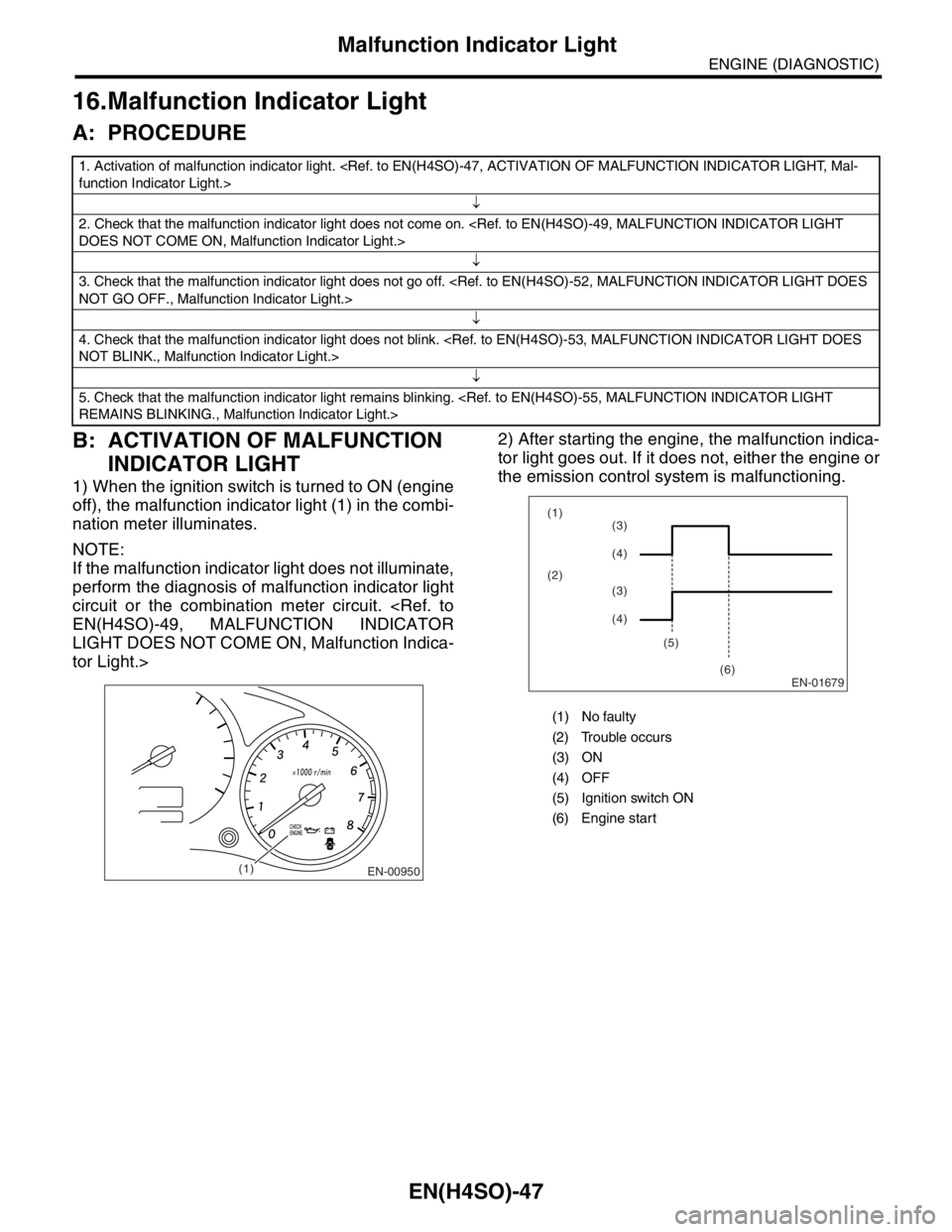
1) When the ignition switch is turned to ON (engine
off), the malfunction indicator light (1) in the combi-
nation meter illuminates.
NOTE:
If the malfunction indicator light does not illuminate,
perform the diagnosis of malfunction indicator light
circuit or the combination meter circuit.
LIGHT DOES NOT COME ON, Malfunction Indica-
tor Light.>2) After starting the engine, the malfunction indica-
tor light goes out. If it does not, either the engine or
the emission control system is malfunctioning.
1. Activation of malfunction indicator light.
↓
2. Check that the malfunction indicator light does not come on.
↓
3. Check that the malfunction indicator light does not go off.
↓
4. Check that the malfunction indicator light does not blink.
↓
5. Check that the malfunction indicator light remains blinking.
EN-00950(1)
(1) No faulty
(2) Trouble occurs
(3) ON
(4) OFF
(5) Ignition switch ON
(6) Engine start
EN-01679
(1)
(2)
(5)
(6)(3)
(4)
(3)
(4)
Page 1146 of 2870

EN(H4SO)-48
ENGINE (DIAGNOSTIC)
Malfunction Indicator Light
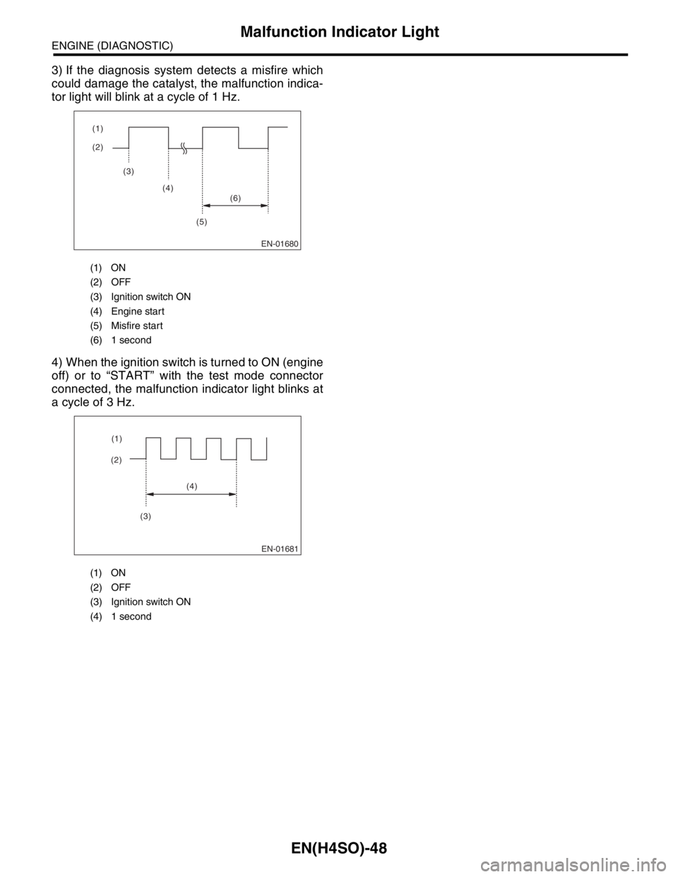
3) If the diagnosis system detects a misfire which
could damage the catalyst, the malfunction indica-
tor light will blink at a cycle of 1 Hz.
4) When the ignition switch is turned to ON (engine
off) or to “START” with the test mode connector
connected, the malfunction indicator light blinks at
a cycle of 3 Hz.
(1) ON
(2) OFF
(3) Ignition switch ON
(4) Engine start
(5) Misfire start
(6) 1 second
(1) ON
(2) OFF
(3) Ignition switch ON
(4) 1 second
EN-01680
(2) (1)
(3)
(4)
(5)(6)
EN-01681
(2)(1)
(4)
(3)