Page 2443 of 4264
ENGINE MECHANICAL (C24SE) 6A-23
Toothed Belt Tension, Adjust
(Engines with toothed belt tension
roller)
Removal
Refer to 6A-21. Toothed Belt and Timing check and removal
steps.
Adjust
1. Loosen the fastening bolt of the toothed belt tension
roller.
2. Turn the toothed belt tension roller at adjustment
eccentric (1) in the direction of arrow (counterclockwise),
until pointer (2) comes to the right stop.
3. If necessary tighten the fastening bolt of toothed belt
tension roller.
4. Rotate the crankshaft twice (720�
) in the engine
rotational direction until marks (2) and (1) align again.
5. Turn the eccentric in the direction of arrow (clockwise)
until pointer (1) and notch (2) are positioned to suit age of
toothed belt.
6. Rotate the crankshaft twice (720�
) in the engine
rotational direction again and correct adjustment if
necessary.
Installation
Refer to 6A-21. Toothed Belt and Timing check and installation
steps.
Page 2445 of 4264
ENGINE MECHANICAL (C24SE) 6A-25
Adjust
Loosen the fastening bolt of the toothed belt tension roller and
turn the adjustment eccentric in the direction of arrow
(clockwise) until pointer (1) comes to the left stop.
Remove the toothed belt.
Installation
1. Install a new toothed belt while keeping tension side taut.
Adjust
Toothed belt tension - see operation " Toothed Belt Tension".
2. Install the toothed belt to the cover.
3. Install the crankshaft pulley while counterholding on the
fastening bolt of toothed belt drive gear.
4. Install the fan shroud.
5. Install the fan belt.
6. Install the V-belt for A/C.
7. Install the V-belt for power steering.
8. Install the fan.
9. Install the belts to the bracket for alternator.
Page 2564 of 4264

6D3-10 STARTING AND CHARGING SYSTEM
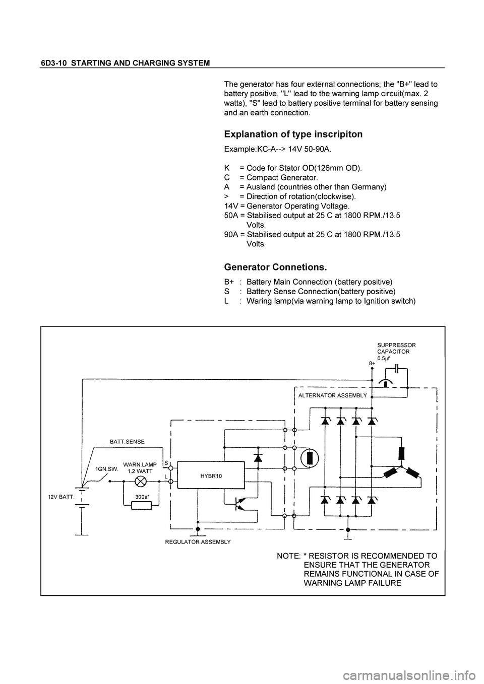
The generator has four external connections; the "B+" lead to
battery positive, "L" lead to the warning lamp circuit(max. 2
watts), "S" lead to battery positive terminal for battery sensing
and an earth connection.
Explanation of type inscripiton
Example:KC-A--> 14V 50-90A.
K = Code for Stator OD(126mm OD).
C = Compact Generator.
A = Ausland (countries other than Germany)
> = Direction of rotation(clockwise).
14V = Generator Operating Voltage.
50A = Stabilised output at 25 C at 1800 RPM./13.5
Volts.
90A = Stabilised output at 25 C at 1800 RPM./13.5
Volts.
Generator Connetions.
B+ : Battery Main Connection (battery positive)
S : Battery Sense Connection(battery positive)
L : Waring lamp(via warning lamp to Ignition switch)
BATT.SENSE
REGULATOR ASSEMBLYHYBR10ALTERNATOR ASSEMBLY
12V BATT.1GN.SW.
300a* WARN.LAMP
1.2 WATT
L S8+SUPPRESSOR
CAPACITOR
0.5�
f
NOTE: * RESISTOR IS RECOMMENDED TO
ENSURE THAT THE GENERATOR
REMAINS FUNCTIONAL IN CASE OF
WARNING LAMP FAILURE
Page 2938 of 4264
2B-6 SHEET METAL
Important Operations - Installation
4. Control Cable
Reroute the control cable to its original position, and check and
see if the lock assembly and control lever work normally.
2. Engine Hood Lock Assembly
Adjustment
1) Install the engine hood lock assembly (4) and temporaril
y
tighten the bolts securing it.
2) Close the hood.
3) Position the hood so that the stepped portion between the
hood (1) and the fender (2) is precisely 1.5 mm (0.06 in)
high.
4) Final tighten the bolts securing the engine hood lock
assembly.
5) Turn the buffers (3) counterclockwise until the stepped
portion between the hood and the fender disappears.
6) Tighten the hood lock assembly fixing bolts to the specified
torque.
Torque N�
m(kgf�
m/lb�
in)
10 (1.0
/ 87)
Page 2977 of 4264
GENERAL INFORMATION 0A-5
7. Measurement criteria are defined by the terms "standard" and "limit".
A measurement falling within the "standard" range indicates that the applicable part or parts are serviceable.
"Limit" is an absolute value.
A measurement falling outside the "limit" indicates that the applicable part or parts must be repaired or replaced.
8. Components are parts are listed in the singular form throughout the Workshop Manual.
9. The following directional criteria are used throughout the Workshop Manual:
Front:
The cooling fan side of the engine.
Right:
The right-hand side of the engine viewed from the flywheel.
Left:
The left-hand side of the engine viewed from the flywheel.
Rear:
The flywheel side of the engine.
Cylinder numbers are counted from the front of the engine towards the rear.
The engine's rotation is clockwise viewed from the front of the engine.
Page 3042 of 4264

1-32 HEATER AND AIR CONDITIONING
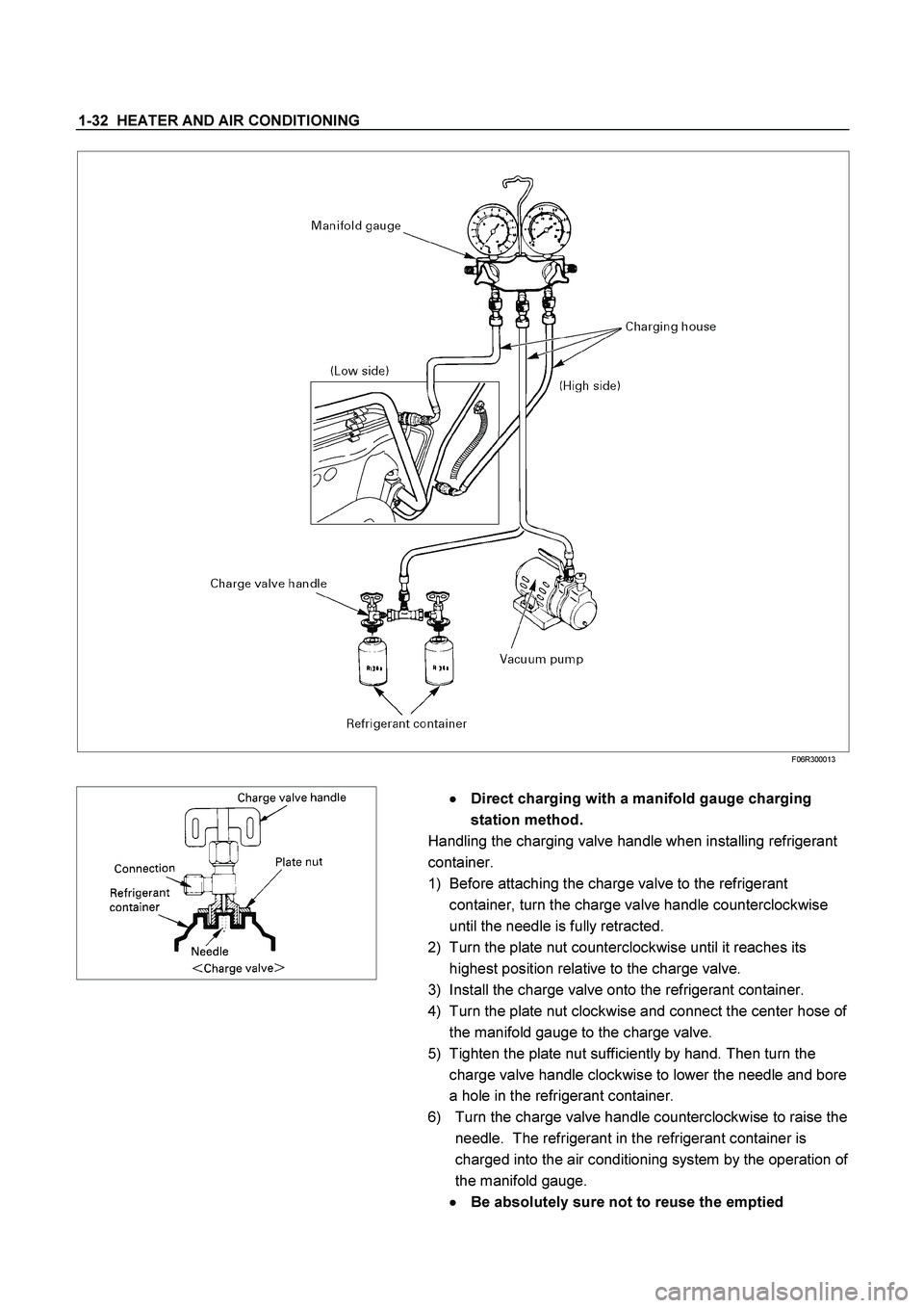
F06R300013
�
�� � Direct charging with a manifold gauge charging
station method.
Handling the charging valve handle when installing refrigerant
container.
1) Before attaching the charge valve to the refrigerant
container, turn the charge valve handle counterclockwise
until the needle is fully retracted.
2) Turn the plate nut counterclockwise until it reaches its
highest position relative to the charge valve.
3) Install the charge valve onto the refrigerant container.
4) Turn the plate nut clockwise and connect the center hose of
the manifold gauge to the charge valve.
5) Tighten the plate nut sufficiently by hand. Then turn the
charge valve handle clockwise to lower the needle and bore
a hole in the refrigerant container.
6) Turn the charge valve handle counterclockwise to raise the
needle. The refrigerant in the refrigerant container is
charged into the air conditioning system by the operation of
the manifold gauge.
�
�� � Be absolutely sure not to reuse the emptied
Page 3043 of 4264

HEATER AND AIR CONDITIONING 1-33
refrigerant container.
1) Make sure the evacuation process is correctly completed.
2) Connect the center-hose of the manifold gauge to the
refrigerant container.
�
�� �
Turn the charge valve handle counterclockwise to purge
to the charging line and purge any air exiting in the
center-hose of the manifold gauge.
3) Open the low-pressure hand valve and charge the
refrigerant about 200 g (0.44 lbs.).
�
�� �
Make sure the high-pressure hand valve is closed.
�
�� �
Avoid charging the refrigerant by turning the refrigerant
container upside down.
4) Close the low-pressure hand valve of the manifold gauge.
�
�� �
Check to ensure that the degree of pressure does not
change.
5) Check the refrigerant leaks by using a HFC-134a leak
detector.
�
�� �
If a leak occurs, repair the leak connection, and start all
over again from the first step of evacuation.
6) If no leaks are found, open the low-pressure hand valve of
the manifold gauge. Then continue charging refrigerant to
the system.
�
�� �
When charging the system becomes difficult:
(1) Run the engine at Idling and close the all vehicle
doors.
(2) A/C switch is "ON".
(3) Set the fan control knob (fan switch) to its highest
position.
(4) Set air soure selector lever to “RECIRC”
WARNING
BE ABSOLUTELY SURE NOT TO OPEN THE HIGH-
PRESSURE HAND VALVE. SHOULD THE HIGH-
PRESSURE HAND VALVE BE OPENED, THE HIGH-
PRESSURE REFRIGERANT GAS WOULD FLOW
BACKWARD, AND THIS MAY CAUSE THE REFRIGERANT
CONTAINER TO BURST.
7) When the refrigerant container is emptied, use the following
procedure to replace it with a new refrigerant container.
(1) Close the low-pressure hand valve.
(2) Raise the needle upward and remove the charge valve.
(3) Reinstall the charge valve to the new refrigerant
container.
(4) Purge any air existing in the center hose of the manifold
gauge.
8) Charge the system to the specified amount and then close
the low-pressure hand valve.
Refrigerant Amount g(lbs.)
720 (1.59)
Page 3085 of 4264
HEATER AND AIR CONDITIONING 1-75
Important Operation - Removal
1. Control lever assembly
Refer to “CONTROL LEVER ASSEMBLY” in this section.
2. Illumination Bulb
To remove the illumination bulb, insert an ordinary screwdriver
into the slot (B) at the back of the bulb. Turn the bulb
counterclockwise and pull it free.