Page 495 of 4264
PARKING BRAKE SYSTEM 5D-5
Front Parking Brake Cable
Front Parking Brake Cable and Associated Parts (Bench Seat)
750R300003
Legend
(1)
Shift Knob (manual transmission)
(2)
Front Floor Console
(3)
Rear Cover
(4)
Bolt
(5)
Seat Assembly
(6)
Buckle: side seat and Center Seat Belt
(7)
Seat Adjuster
Page 536 of 4264
10-28 CAB
INSTRUMENT PANEL
REMOVAL
This illustration is based on RHD model
RTW4A0LF001001
Disassembly Steps
� 1. Front console assembly
� 2. Glove box
� 3. Instrument panel driver lower cover
assembly
� 4. Driver knee bolster assembly
� 5. Driver air bag
� 6. Steering wheel/ steering cowl
� 7. Meter cluster assembly
8. Dash side trim cover
9. Front pillar trim cover
10. Front cover
11. Side cover
� 12. Instrument panel & Cross beam
assembly
�
13. Ashtray case
� 14. Center cluster assembly
� 15. Control lever assembly
16. Storage box assembly
� 17. Ashtray bracket
18. Meter assembly
19. Passenger lower bracket
20. Glove box cover
� 21. Passenger air bag (if so equipped)
� 22. Side ventilation grille
� 23. Vent duct assembly/Defroster nozzle
assembly
24. Instrument harness assembly
� 25. Instrument panel
� 26. Cross beam
Page 540 of 4264
10-32 CAB
INSTALLATION
This illustration is based on RHD model
RTW4A0LF001101
Installation Steps
1. Cross beam
2. Instrument panel
3. Instrument harness assembly
4. Vent duct assembly/Defroster nozzle
assembly
5. Side ventilation grille
6. Passenger air bag
7. Glove box cover
8. Passenger lower bracket
9. Meter assembly
10. Ashtray bracket
11. Storage box assembly
12. Control lever assembly
13. Center cluster assembly
14. Ashtray case
� 15. Instrument panel & Cross beam
assembly
16. Side cover
17. Front cover
18. Front pillar trim cover
19. Dash side trim cover
20. Meter cluster assembly
� 21. Steering wheel/Steering cowl
22. Driver air bag
23. Driver knee bolster assembly
24. Instrument panel driver lower cover assembly
25. Glove box
26. Front console assembly
Page 2516 of 4264

6B-6 ENGINE COOLING
Draining and Refilling Cooling
System
Before draining the cooling system, inspect the system and
perform any necessary service to ensure that it is clean, does
not leak and is in proper working order. The engine coolant
(EC) level should be between the "MIN" and "MAX" lines of
reserve tank when the engine is cold. If low, check for leakage
and add EC up to the "MAX" line. There should not be any
excessive deposit of rust or scales around the radiator cap or
radiator filler hole, and the EC should also be free from oil.
Replace the EC if excessively dirty.
1. Completely drain the cooling system by opening the drain
plug at the bottom of the radiator.
2. Remove the radiator cap.
WARNING: TO AVOID THE DANGER OF BEING BURNED,
DO NOT REMOVE THE CAP WHILE THE ENGINE AND
RADIATOR ARE STILL HOT. SCALDING FLUID AND
STEAM CAN BE BLOWN OUT UNDER PRESSURE.
3. Disconnect all hoses from the EC reserve tank.
Scrub and clean the inside of the reserve tank with soap
and water. Flush it well with clean water, then drain it. Install
the reserve tank and hoses.
4. Refill the cooling system with the EC using a solution that is
at least 50 percent antifreeze.
5. Fill the radiator to the base of the filler neck.
Fill the EC reserve tank to "MAX" line when the engine is
cold.
6. Block the drive wheels and firmly apply the parking brake.
Shift an automatic transmission to "P" (Park) or a manual
transmission to neutral.
7. Remove the radiator cap. Start the engine and warm it up a
t
2,500 - 3,000 rpm for about 30 minutes.
8. When the air comes out from the radiator filler neck and the
EC level has gone down, replenish with the EC. Repeat this
procedure until the EC level does not go down. Then stop
the engine and install the radiator cap. Let the engine cool
down.
9. After the engine has cooled, replenish with EC up to the
"MAX" line of the reserve tank.
10. Start the engine. With the engine running at 3,000 rpm,
make sure there is no running water sound from the heate
r
core (behind the center console).
11. If the running water sound is heard, repeat steps 8 to 10.
Page 3079 of 4264
HEATER AND AIR CONDITIONING 1-69
REAR HEATER DUCT
REMOVAL AND INSTALLATION
This illustration is based on RHD model
RTW410LF001301
Disassembly Steps
1. Front seat assembly (RH/LH)
� Refer to SECTION 10 “FRONT SEAT”
2. Rear floor console
�
Refer to SECTION 10 “FLOOR
CONSOLE”
3. Front floor console (A/T, M/T Model)
�
Refer to SECTION 10 “FLOOR
CONSOLE”
4. Sill plate (RH/LH)
� Refer to SECTION 10 “INTERIOR
TRIM PANELS”
5. Dash side trim cover (RH/LH)
6. Carpet
7. Clip
8. Rear Heater duct (RH/LH)
9. Rear Heater duct center
Reassembly Steps
9. Rear heater duct center
8. Rear heater duct (RH/LH)
7. Clip
6. Carpet
5. Dash side trim cover (RH/LH)
4. Sill plate (RH/LH)
�
Refer to SECTION 10 “INTERIOR
TRIM PANELS”
3. Front floor console (A/T, M/T Model)
� Refer to SECTION 10 “FLOOR
CONSOLE”
2. Rear floor console
�
Refer to SECTION 10 “FLOOR
CONSOLE”
1. Front seat assembly (RH/LH)
�
Refer to SECTION 10 “FRONT SEAT”
Page 3181 of 4264

MANUAL TRANSMISSION 7B1-17
14. Install the exhaust pipe (8). (6VE1)
Torque: 67 N�
�� �m (6.8 kg�
�� �m/49 lb�
�� �ft)
RTW37ASH000101
15. Install rear propeller shaft (6).
Torque: 63 N�
�� �m (6.4 kg�
�� �m/46 lb�
�� �ft)
16. Install center bearing on crossemember.
Torque: 69 N�
�� �m (7.0 kg�
�� �m/51 lb�
�� �ft)
17. Install gear control lever (5).
Torque: 19 N�
�� �m (1.9 kg�
�� �m/14 lb�
�� �ft)
18. Install grommet assembly (4).
Torque: Screw 1.4 N�
�� �m (0.14 kg�
�� �m/12 lb�
�� �in)
Nut 7 N�
�� �m (0.7 kg�
�� �m/61 lb�
�� �in)
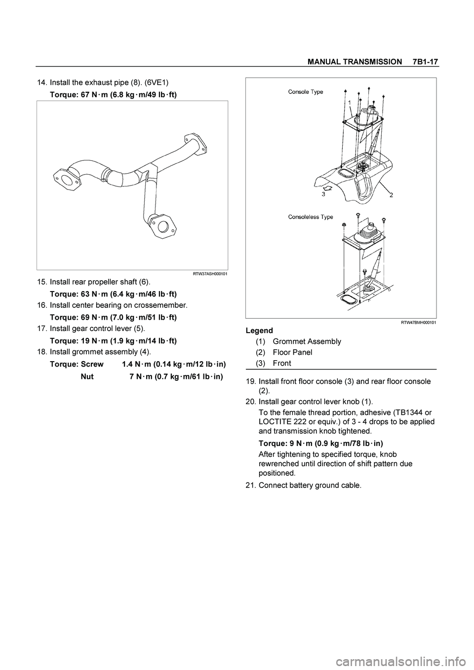
RTW47BMH000101
Legend
(1) Grommet Assembly
(2) Floor Panel
(3) Front
19. Install front floor console (3) and rear floor console
(2).
20. Install gear control lever knob (1).
To the female thread portion, adhesive (TB1344 or
LOCTITE 222 or equiv.) of 3 - 4 drops to be applied
and transmission knob tightened.
Torque: 9 N�
�� �m (0.9 kg�
�� �m/78 lb�
�� �in)
After tightening to specified torque, knob
rewrenched until direction of shift pattern due
positioned.
21. Connect battery ground cable.