Page 174 of 4264
4B-10 REAR AXLE
Disassembly
�
Raise vehicle to the working level.
�
Support the axle assembly with the proper jack
and chassis stands.
�
Remove wheel and tire.
�
Drain differential oil.
�
Remove propeller shaft. (Refer to the section
“Rear Propeller Shaft”.)
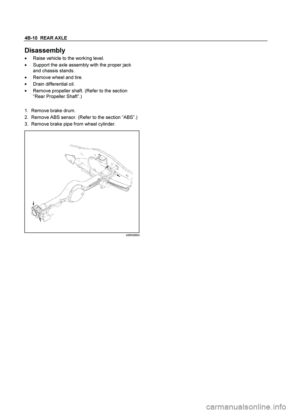
1.
Remove brake drum.
2. Remove ABS sensor. (Refer to the section “ABS”.)
3. Remove brake pipe from wheel cylinder.
420R300003
Page 214 of 4264
4B-50 REAR AXLE
3. OIL LEAKAGE
1) Differential Carrier Leakage
Checkpoint Trouble Cause Countermeasure
Correct the oil levelToo much gear oil NG
Reapply the liquid gasket
and/or tighten the lock nut to
the specified torque
Reapply the liquid gasket
Tighten the bolts to the
specified torque
Replace the oil seal
Ring gear thrust boltLoose lock nut and/or liquid
Liquid gasket seal bed
Loose bolts
Oil sealWorn or defective oil seal
Differential carrier
Clean the air breatherAir breatherClogged air breather
NG NG NG NG NG
OK OK OK
OK
Gear oil level
Page 290 of 4264
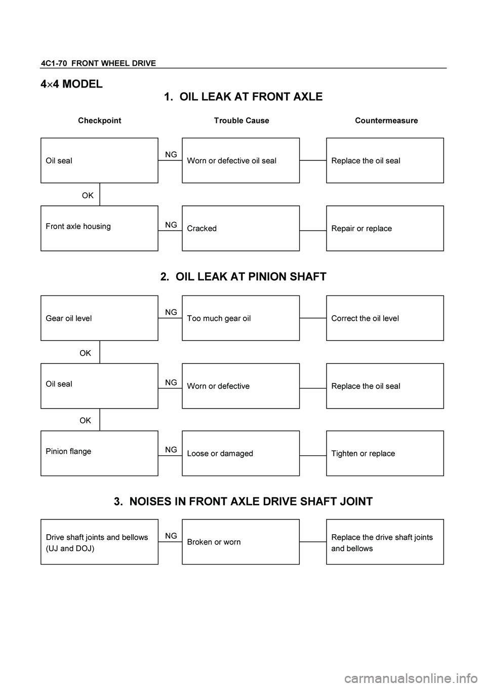
4C1-70 FRONT WHEEL DRIVE
4�
�� �
4 MODEL
1. OIL LEAK AT FRONT AXLE
Checkpoint Trouble Cause Countermeasure
Front axle housingRepair or replaceCracked
Replace the oil sealWorn or defective oil seal
NG NG
OKOil seal
2. OIL LEAK AT PINION SHAFT
Oil sealReplace the oil sealWorn or defective
Correct the oil levelToo much gear oil
NG NG
OKGear oil level
Pinion flangeTighten or replaceLoose or damaged NG OK
3. NOISES IN FRONT AXLE DRIVE SHAFT JOINT
Replace the drive shaft joints
and bellows
Broken or worn
NG
Drive shaft joints and bellows
(UJ and DOJ)
Page 291 of 4264
FRONT WHEEL DRIVE 4C1-71
4. NOISES IN FRONT AXLE
Checkpoint Trouble Cause Countermeasure
Replenish the gear oilInsufficient gear oil NG
Replace the wheel bearing
Replace the pinion shaft
bearing
Replace the ring gear pinion
gear or side gear
Replace the gear oil
Wheel bearingWorn
Pinion shaft bearingWorn
Worn or chipped
Wrong or poor grade gear oil
Ring gear, pinion gear or side
gear
Adjust the backlashDrive pinion to ring gear
backlashToo much or too little backlash
NG NG NG NG NG
OK OK
OK
OK
Oil level
Tighten or replaceDifferential bearingLoose or worn NG OK
Page 344 of 4264

5A-28 BRAKE CONTROL SYSTEM
Isolation Valve Test
Purpose: The purpose of this test is to detect brake
pipe and valve line harness wire for wrong connections
and valve trouble.
This test will help you confirm the result of your repair
service including the removal/reinstallation of brake
pipe, valve line harness and valve.
Test conditions: The ignition key is in the “ON” position
with the four wheels lifted up. The brake pedal is
stepped on, released and stepped on again with the
parking brake released.
Test procedure:
1. Connect Tech 2 with the vehicle, and select
Actuaor Test from the menus.
2. Select a Solenoid Valve Test Menu from the
Actuaor Test Menus.
060L300002
3. Select Isolation Valve from the Valve Select Menus.
4. Step on the brake pedal.
5. Release the brake pedal.
6. Make sure that the Isolation Valve “ON” aimed at by
Tech 2 and the wheel locked position are the same.
If different, check brake pipe, valve line harness
wiring and H/UNIT. Repair is needed if abnormality
is found.
7. Conduct Step 2 through Step 5 above on all the
four wheels.
060L300002
CAUTION: When conducting this test, please
observe the following cautions.
1. Do not start the engine.
2. Lift up the vehicle at a level floor.
�
�� � Secure a clearance from the floor surface
enough to allow the lifted tire to rotate.
3. Maintain the lift up.
4. Wipe the floor surface to remove water and oil
so that the surface may become unslippery.
5. Do not load the vehicle.
�
�� � When lifting up the vehicle, be sure to
observe the lifting up points. Refer to
vehicle lifting points in 0A section.
Page 345 of 4264

BRAKE CONTROL SYSTEM 5A-29
Dump Valve Test
Purpose: The purpose of this test is to detect brake
pipe and valve line harness wire for wrong connections
and valve trouble.
This test will help you confirm the result of your repai
r
service including the removal/reinstallation of brake
pipe, valve line harness and valve.
Test conditions: The ignition key is in the “ON” position
with the four wheels lifted up. The brake pedal is
stepped on, released and stepped on again with the
parking brake released.
Test procedure:
1. Connect Tech 2 with the vehicle, and select
Actuator Test Function from the menus.
2. Select a Solenoid Valve Test Menu from the
Actuator Test Menus.
060L300002
3. Select Dump Valve from the Valve Select Meuns.
4. Step on the brake pedal.
5. Make sure that the Dump Valve “ON” aimed at by
Tech 2 and the wheel released position are the
same. If different, check brake pipe, valve line
harness wiring and H/UNIT. Repair is needed if
abnormality is found.
6. Conduct Step 2 through Step 5 above on all the
four wheels.
060L300002
CAUTION: When conducting this test, please
observe the following cautions.
1. Do not start the engine.
2. Lift up the vehicle at a level floor.
�
�� � Secure a clearance from the floor surface
enough to allow the lifted tire to rotate.
3. Maintain the lift up.
4. Wipe the floor surface to remove water and oil
so that the surface may become unslippery.
5. Do not load the vehicle.
�
�� � When lifting up the vehicle, be sure to
observe the lifting up points. Refer to
vehicle lifting points in 0A section.
Page 451 of 4264

BRAKES 5C-25
Filling Master Cylinder Reservoir
CAUTION :
Use only specified brake fluid. Do not use any fluid which
contains a petroleum base. Do not use a container which
has been used for petroleum based fluids or a container
which is wet with water. Petroleum based fluid will cause
swelling and distortion of rubber parts in the hydraulic
brake system. Water mixed with brake fluid lowers the
fluid boiling point. Keep all fluid containers capped to
prevent contamination.
Always fill the master cylinder reservoir when the engine
is cold.
Never allow the brake fluid to come in contact with the
painted surfaces.
The master cylinder reservoir must be kept properly filled
to ensure adequate reserve and to prevent air and
moisture from entering the hydraulic system. However,
because of expansion due to heat absorbed from the
brakes and the engine, the reservoir must not be
overfilled. Thoroughly clean reservoir cap before removal
to avoid getting dirt into reservoir. Add fluid as required to
bring level to the “MAX” mark on the reservoir tank. Use
“DOT 3” Hydraulic Brake Fluid.
Leakage of Brake Fluid
With engine idling, set shift lever in the neutral position and
continue to depress brake pedal at a constant pedal
application force.
Should the pedal stroke become deeper gradually, leakage
from the hydraulic pressure system is possible.
Make sure by visual check that there is no leak.
BLEEDING OF THE BRAKE HYDRAULIC
CIRCUIT
If air enters the bake lines, it will cause poor brake action.
Therefore, bleeding should be performed if the brakes have
been used with the level of brake fluid in the reservoir
excessively low or if brake pipes have been disconnected in
the course of brake servicing.
Bleeding operation calls for co-operative action of 2 persons.
�
Set the parking brake firmly while bleeding.
�
Perform bleeding operation with ENGINE RUNNING, to
prevent damage to push rod seal.
Make sure exhaust is suitably ventilated.
�
Bleed the hydraulic system with the fluid reservoir filled to
the specified level.
�
Bleed the system starting with the rear wheel cylinde
r
farthest from the master cylinder.
Page 919 of 4264

ELECTRICAL-BODY AND CHASSIS 8A-261
2. Even when the parking brake lever is pulled, the indicator light does not go off
Checkpoint Trouble Cause Countermeasure
Adjust the SW. installation
position or replace the parking
brake SW. Incorrect the parking brake
SW. adjustment or brake SW.
faulty
NG Thermo unit malfunction
Replace the brake fluid level
SW., or vacuum SW., or
repair a short circuit between
the parking brake SW.
connector 1
C-39
(Lever: 1
R-4) and 9 B-23
or the brake fluid level SW.
connector 2
C-37 and 9
B-23, (or the vacuum SW.
connector 1
C-38 and 9
B-23 : 4JH1-TC ONLY)
Check to see if the indicator
light goes off when the parking
brake SW. connector 1
C-39
(Lever: 1
R-4) is
di t d
Brake fluid level SW. or
vacuum SW. faulty or short
circuit
NG OK
Parking brake SW. installation
position and function
3. Oil pressure warning light does not go off while engine is running
Refer to ENGINE Section
Refer to ENGINE Section
NG Thermo unit malfunction
Repair a short circuit between
1
E-1 and 3 B-24
Check to see the warning light
goes off when the oil pressure
SW. connector
1
E-1 is disconnected
Short circuit
Replace the oil pressure unit
(or the oil pressure SW.)
Continuity between the oil
pressure SW. connector
1
E-1 and the body ground
when the engine is operating
Oil pressure unit (or oil
pressure SW) faulty
NG NG OK
OK
Engine oil pressure
 Differential Carrier Leakage
Checkpoint Trouble Cause Countermeasure
Correct the oil levelToo much gear oil NG
Reapply the liquid gasket
and/or tighten")