2004 ISUZU TF SERIES oil level
[x] Cancel search: oil levelPage 1122 of 4264
6 – 2 TROUBLESHOOTING
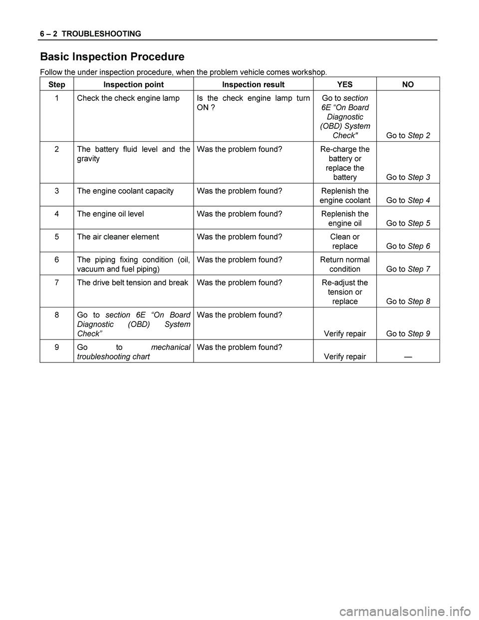
Basic Inspection Procedure
Follow the under inspection procedure, when the problem vehicle comes workshop.
Step Inspection point Inspection result YES NO
1 Check the check engine lamp Is the check engine lamp turn
ON ? Go to section
6E “On Board
Diagnostic
(OBD) System
Check" Go to Step 2
2 The battery fluid level and the
gravity Was the problem found? Re-charge the
battery or
replace the
battery Go to Step 3
3 The engine coolant capacity Was the problem found? Replenish the
engine coolant Go to Step 4
4 The engine oil level Was the problem found? Replenish the
engine oil Go to Step 5
5 The air cleaner element Was the problem found? Clean or
replace Go to Step 6
6 The piping fixing condition (oil,
vacuum and fuel piping) Was the problem found? Return normal
condition Go to Step 7
7 The drive belt tension and break Was the problem found? Re-adjust the
tension or
replace Go to Step 8
8 Go to section 6E “On Board
Diagnostic (OBD) System
Check” Was the problem found?
Verify repair Go to Step 9
9 Go to mechanical
troubleshooting chart Was the problem found?
Verify repair —
Page 1129 of 4264
TROUBLESHOOTING 6 – 9
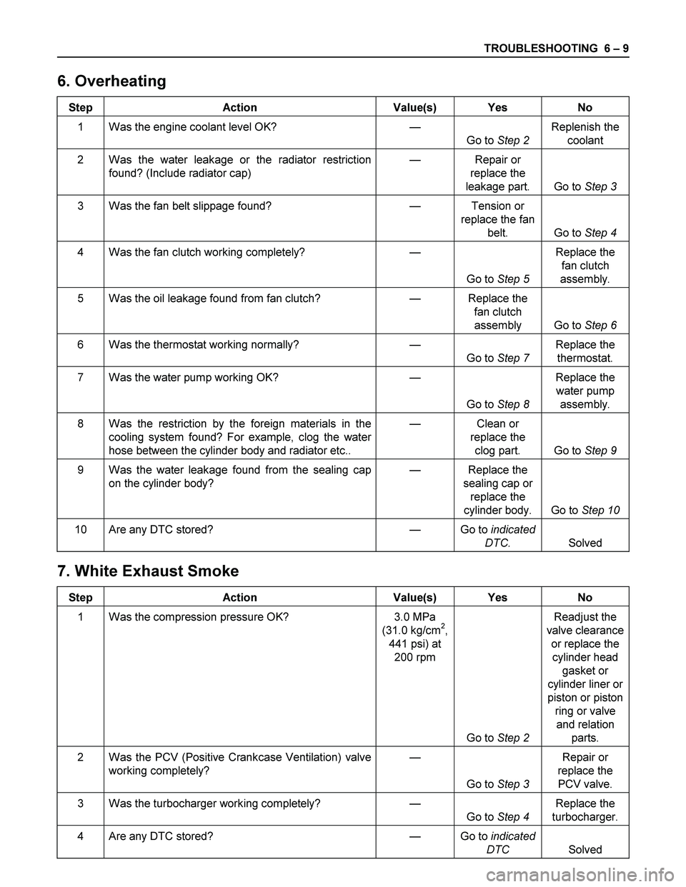
6. Overheating
Step Action Value(s) Yes No
1 Was the engine coolant level OK? —
Go to Step 2 Replenish the
coolant
2 Was the water leakage or the radiator restriction
found? (Include radiator cap) — Repair or
replace the
leakage part. Go to Step 3
3 Was the fan belt slippage found? — Tension or
replace the fan
belt. Go to Step 4
4 Was the fan clutch working completely? —
Go to Step 5 Replace the
fan clutch
assembly.
5 Was the oil leakage found from fan clutch? — Replace the
fan clutch
assembly Go to Step 6
6 Was the thermostat working normally? —
Go to Step 7 Replace the
thermostat.
7 Was the water pump working OK? —
Go to Step 8 Replace the
water pump
assembly.
8 Was the restriction by the foreign materials in the
cooling system found? For example, clog the water
hose between the cylinder body and radiator etc.. — Clean or
replace the
clog part. Go to Step 9
9 Was the water leakage found from the sealing cap
on the cylinder body? — Replace the
sealing cap or
replace the
cylinder body. Go to Step 10
10 Are any DTC stored? — Go to indicated
DTC. Solved
7. White Exhaust Smoke
Step Action Value(s) Yes No
1 Was the compression pressure OK? 3.0 MPa
(31.0 kg/cm2,
441 psi) at
200 rpm
Go to Step 2 Readjust the
valve clearance
or replace the
cylinder head
gasket or
cylinder liner or
piston or piston
ring or valve
and relation
parts.
2 Was the PCV (Positive Crankcase Ventilation) valve
working completely? —
Go to Step 3 Repair or
replace the
PCV valve.
3 Was the turbocharger working completely? —
Go to Step 4 Replace the
turbocharger.
4 Are any DTC stored? — Go to indicated
DTC Solved
Page 1136 of 4264
6 – 16 TROUBLESHOOTING
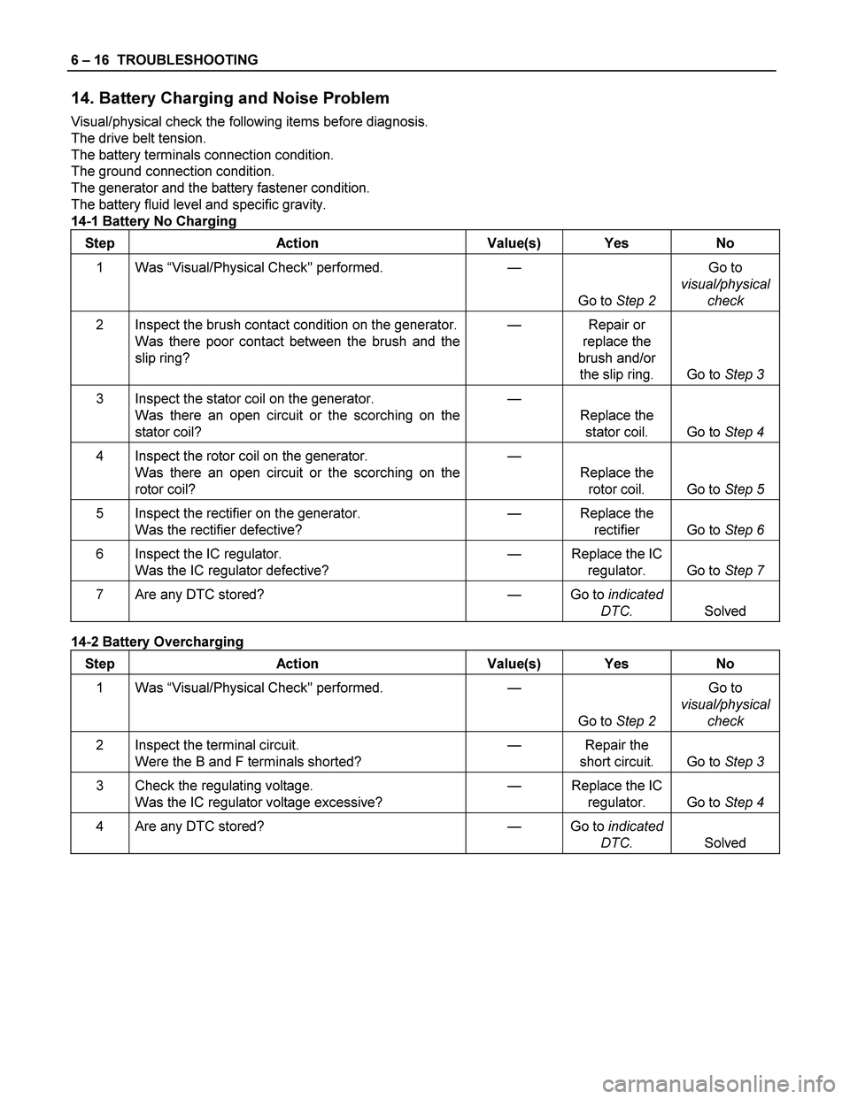
14. Battery Charging and Noise Problem
Visual/physical check the following items before diagnosis.
The drive belt tension.
The battery terminals connection condition.
The ground connection condition.
The generator and the battery fastener condition.
The battery fluid level and specific gravity.
14-1 Battery No Charging
Step Action Value(s) Yes No
1 Was “Visual/Physical Check" performed.
—
Go to Step 2 Go to
visual/physical
check
2 Inspect the brush contact condition on the generator.
Was there poor contact between the brush and the
slip ring? — Repair or
replace the
brush and/or
the slip ring. Go to Step 3
3 Inspect the stator coil on the generator.
Was there an open circuit or the scorching on the
stator coil? —
Replace the
stator coil. Go to Step 4
4 Inspect the rotor coil on the generator.
Was there an open circuit or the scorching on the
rotor coil? —
Replace the
rotor coil. Go to Step 5
5 Inspect the rectifier on the generator.
Was the rectifier defective? — Replace the
rectifier Go to Step 6
6 Inspect the IC regulator.
Was the IC regulator defective? — Replace the IC
regulator. Go to Step 7
7 Are any DTC stored? — Go to indicated
DTC. Solved
14-2 Battery Overcharging
Step Action Value(s) Yes No
1 Was “Visual/Physical Check" performed.
—
Go to Step 2 Go to
visual/physical
check
2 Inspect the terminal circuit.
Were the B and F terminals shorted? — Repair the
short circuit. Go to Step 3
3 Check the regulating voltage.
Was the IC regulator voltage excessive? — Replace the IC
regulator. Go to Step 4
4 Are any DTC stored? — Go to indicated
DTC. Solved
Page 1139 of 4264
TROUBLESHOOTING 6 – 19
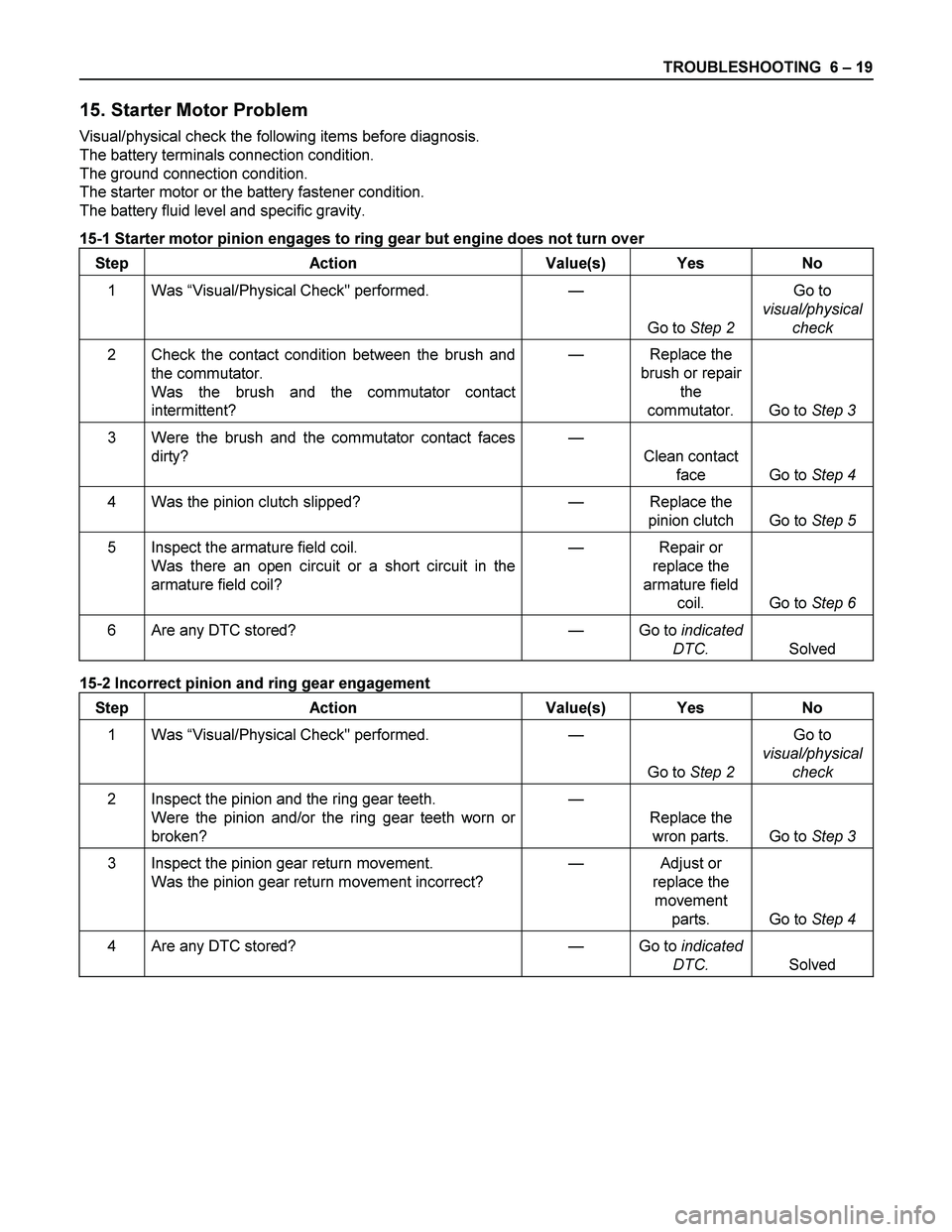
15. Starter Motor Problem
Visual/physical check the following items before diagnosis.
The battery terminals connection condition.
The ground connection condition.
The starter motor or the battery fastener condition.
The battery fluid level and specific gravity.
15-1 Starter motor pinion engages to ring gear but engine does not turn over
Step Action Value(s) Yes No
1 Was “Visual/Physical Check" performed.
—
Go to Step 2 Go to
visual/physical
check
2 Check the contact condition between the brush and
the commutator.
Was the brush and the commutator contact
intermittent? — Replace the
brush or repair
the
commutator. Go to Step 3
3 Were the brush and the commutator contact faces
dirty?
—
Clean contact
face Go to Step 4
4 Was the pinion clutch slipped? — Replace the
pinion clutch Go to Step 5
5 Inspect the armature field coil.
Was there an open circuit or a short circuit in the
armature field coil? — Repair or
replace the
armature field
coil. Go to Step 6
6 Are any DTC stored? — Go to indicated
DTC. Solved
15-2 Incorrect pinion and ring gear engagement
Step Action Value(s) Yes No
1 Was “Visual/Physical Check" performed.
—
Go to Step 2 Go to
visual/physical
check
2 Inspect the pinion and the ring gear teeth.
Were the pinion and/or the ring gear teeth worn or
broken? —
Replace the
wron parts. Go to Step 3
3 Inspect the pinion gear return movement.
Was the pinion gear return movement incorrect? — Adjust or
replace the
movement
parts. Go to Step 4
4 Are any DTC stored? — Go to indicated
DTC. Solved
Page 1164 of 4264
6A – 24 ENGINE MECHANICAL
SERVICING
Servicing refers to general maintenance procedures to be performed by qualified service personnel.
RTW36ASH000401
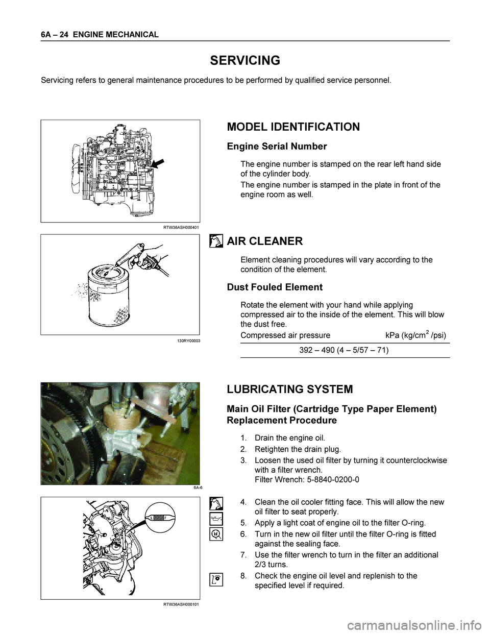
MODEL IDENTIFICATION
Engine Serial Number
The engine number is stamped on the rear left hand side
of the cylinder body.
The engine number is stamped in the plate in front of the
engine room as well.
AIR CLEANER
Element cleaning procedures will vary according to the
condition of the element.
Dust Fouled Element
Rotate the element with your hand while applying
compressed air to the inside of the element. This will blow
the dust free.
Compressed air pressure kPa (kg/cm
2 /psi)
392 – 490 (4 – 5/57 – 71)
LUBRICATING SYSTEM
Main Oil Filter (Cartridge Type Paper Element)
Replacement Procedure
1. Drain the engine oil.
2. Retighten the drain plug.
3. Loosen the used oil filter by turning it counterclockwise
with a filter wrench.
Filter Wrench: 5-8840-0200-0
RTW36ASH000101
4. Clean the oil cooler fitting face. This will allow the new
oil filter to seat properly.
5. Apply a light coat of engine oil to the filter O-ring.
6. Turn in the new oil filter until the filter O-ring is fitted
against the sealing face.
7. Use the filter wrench to turn in the filter an additional
2/3 turns.
8. Check the engine oil level and replenish to the
specified level if required.
130RY00003
6A-6
Page 1167 of 4264
ENGINE MECHANICAL 6A – 27
111R300001
COOLING SYSTEM
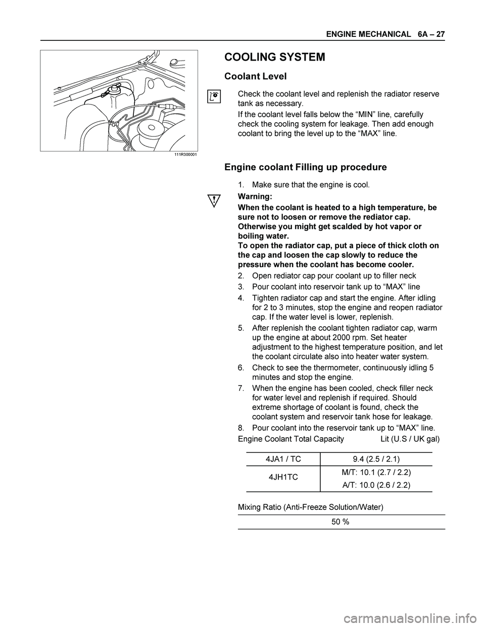
Coolant Level
Check the coolant level and replenish the radiator reserve
tank as necessary.
If the coolant level falls below the “MIN” line, carefully
check the cooling system for leakage. Then add enough
coolant to bring the level up to the “MAX” line.
Engine coolant Filling up procedure
1. Make sure that the engine is cool.
Warning:
When the coolant is heated to a high temperature, be
sure not to loosen or remove the rediator cap.
Otherwise you might get scalded by hot vapor or
boiling water.
To open the radiator cap, put a piece of thick cloth on
the cap and loosen the cap slowly to reduce the
pressure when the coolant has become cooler.
2. Open rediator cap pour coolant up to filler neck
3. Pour coolant into reservoir tank up to “MAX” line
4. Tighten radiator cap and start the engine. After idling
for 2 to 3 minutes, stop the engine and reopen radiator
cap. If the water level is lower, replenish.
5. After replenish the coolant tighten radiator cap, warm
up the engine at about 2000 rpm. Set heater
adjustment to the highest temperature position, and let
the coolant circulate also into heater water system.
6. Check to see the thermometer, continuously idling 5
minutes and stop the engine.
7. When the engine has been cooled, check filler neck
for water level and replenish if required. Should
extreme shortage of coolant is found, check the
coolant system and reservoir tank hose for leakage.
8. Pour coolant into the reservoir tank up to “MAX” line.
Engine Coolant Total Capacity Lit (U.S / UK gal)
4JA1 / TC 9.4 (2.5 / 2.1)
4JH1TC M/T: 10.1 (2.7 / 2.2)
A/T: 10.0 (2.6 / 2.2)
Mixing Ratio (Anti-Freeze Solution/Water)
50 %
Page 1181 of 4264
ENGINE MECHANICAL 6A – 41
Coolant Replenishment
Warning:
When the coolant is heated to a high temperature, be
sure not to loosen or remove the rediator cap.
Otherwise you might get scalded by hot vapor or
boiling water.
To open the radiator cap, put a piece of thick cloth on
the cap and loosen the cap slowly to reduce the
pressure when the coolant has become cooler.
1. Open rediator cap pour coolant up to filler neck
2. Pour coolant into reservoir tank up to "MAX" line
3. Tighten radiator cap and start the engine. After idling
for 2 to 3 minutes, stop the engine and reopen radiator
cap. If the water level is lower, replenish.
4. After replenish the coolant tighten radiator cap, warm
up the engine at about 2000 rpm. Set heater
adjustment to the highest temperature position, and let
the coolant circulate also into heater water system.
5. Check to see the thermometer, continuously idling 5
minutes and stop the engine.
6. When the engine has been cooled, check filler neck for
water level and replenish if required. Should extreme
shortage of coolant is found, check the coolant system
and reservoir tank hose for leakage.
7. Pour coolant into the reservoir tank up to "MAX" line.
Coolant Capacity lit (US/UK gal)
4JA1 / TC 9.4 (2.5 / 2.1)
4JH1TC M/T: 10.1 (2.7 / 2.2)
A/T: 10.0 (2.6 / 2.2)
9.5 (2.5/2.1)
Engine Warm-Up
After completing the required maintenance procedures,
start the engine and allow it to idle until it is warm.
Check the following:
1. Engine idling speed.
2. Engine noise level.
3. Engine lubricating system and cooling system.
Carefully check for oil and coolant leakage.
4. Clutch engagement.
5. Transmission operation.
6. Indicator warning light operation.
Page 1183 of 4264
ENGINE MECHANICAL 6A – 43
ENGINE OVERHAUL
REMOVAL
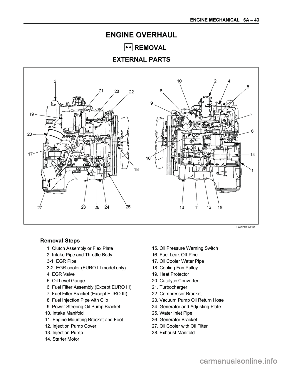
EXTERNAL PARTS
RTW36AMF000401
Removal Steps
1. Clutch Assembly or Flex Plate
2. Intake Pipe and Throttle Body
3-1. EGR Pipe
3-2. EGR cooler (EURO III model only)
4. EGR Valve
5. Oil Level Gauge
6. Fuel Filter Assembly (Except EURO III)
7. Fuel Filter Bracket (Except EURO III)
8. Fuel Injection Pipe with Clip
9. Power Steering Oil Pump Bracket
10. Intake Manifold
11. Engine Mounting Bracket and Foot
12. Injection Pump Cover
13. Injection Pump
14. Starter Motor
15. Oil Pressure Warning Switch
16. Fuel Leak Off Pipe
17. Oil Cooler Water Pipe
18. Cooling Fan Pulley
19. Heat Protector
20. Catalytic Converter
21. Turbocharger
22. Compressor Bracket
23. Vacuum Pump Oil Return Hose
24. Generator and Adjusting Plate
25. Water Inlet Pipe
26. Generator Bracket
27. Oil Cooler with Oil Filter
28. Exhaust Manifold