Page 1185 of 4264
ENGINE MECHANICAL 6A – 45
4JA1�L
RTW46ASH001001
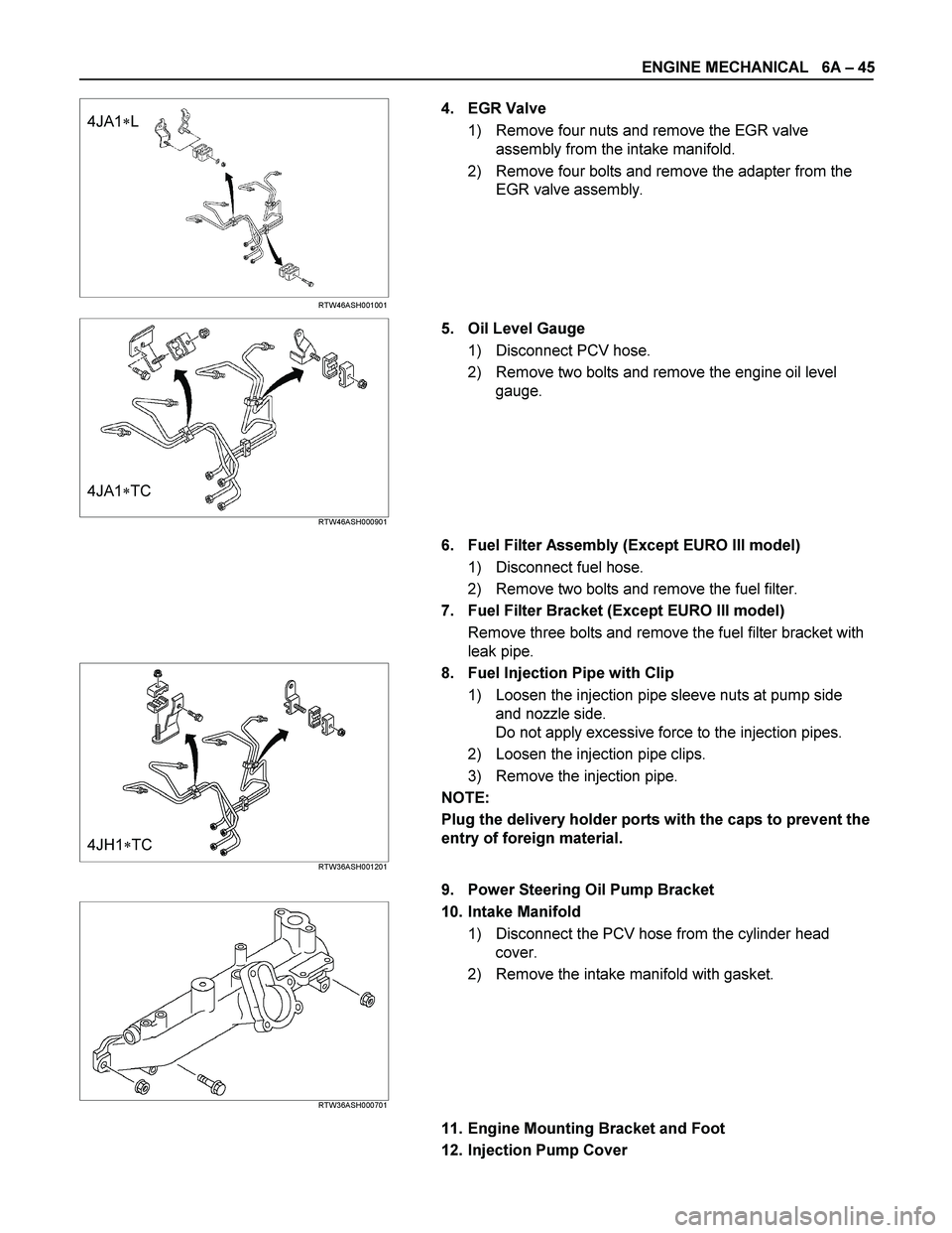
4. EGR Valve
1) Remove four nuts and remove the EGR valve
assembly from the intake manifold.
2) Remove four bolts and remove the adapter from the
EGR valve assembly.
4JA1�TC RTW46ASH000901
5. Oil Level Gauge
1) Disconnect PCV hose.
2) Remove two bolts and remove the engine oil level
gauge.
6. Fuel Filter Assembly (Except EURO III model)
1) Disconnect fuel hose.
2) Remove two bolts and remove the fuel filter.
7. Fuel Filter Bracket (Except EURO III model)
Remove three bolts and remove the fuel filter bracket with
leak pipe.
4JH1�TC RTW36ASH001201
8. Fuel Injection Pipe with Clip
1) Loosen the injection pipe sleeve nuts at pump side
and nozzle side.
Do not apply excessive force to the injection pipes.
2) Loosen the injection pipe clips.
3) Remove the injection pipe.
NOTE:
Plug the delivery holder ports with the caps to prevent the
entry of foreign material.
9. Power Steering Oil Pump Bracket
RTW36ASH000701
10. Intake Manifold
1) Disconnect the PCV hose from the cylinder head
cover.
2) Remove the intake manifold with gasket.
11. Engine Mounting Bracket and Foot
12. Injection Pump Cover
Page 1258 of 4264
6A – 118 ENGINE MECHANICAL
INSTALLATION
EXTERNAL PARTS
RTW36AMF000701
Installation Steps
1.
Exhaust Manifold 18. Engine Mounting Bracket and
2.
Oil Cooler with Oil Filter Foot
3. Generator Bracket 19. Intake Manifold
4. Water Inlet Pipe 20. Power Steering Oil Pump
5.
Generator and Adjusting Plate Bracket
6.
Vacuum Pump Oil Return Hose 21. Fuel Injection Pipe with Clip
7.
Compressor Bracket 22. Fuel Filter Bracket (Except
EURO III)
8. Turbocharger 23. Fuel Filter Assembly (Except
EURO III)
9. Catalytic Converter 24. Oil Level Gauge
10. Heat Protector 25. EGR Valve
11. Cooling Fan Pulley 26-1. EGR Pipe
12. Oil Cooler Water Pipe 26-2. EGR Cooler (EURO III model
only)
13. Fuel Leak Off Pipe 27. Intake Pipe and Throttle Body
(4JA1TC/4JH1TC only)
14. Oil Pressure Warning Switch 28. Clutch Assembly or Flex Plate
15. Starter Motor
16. Injection Pump
17. Injection Pump Cover
Page 1264 of 4264
6A – 124 ENGINE MECHANICAL
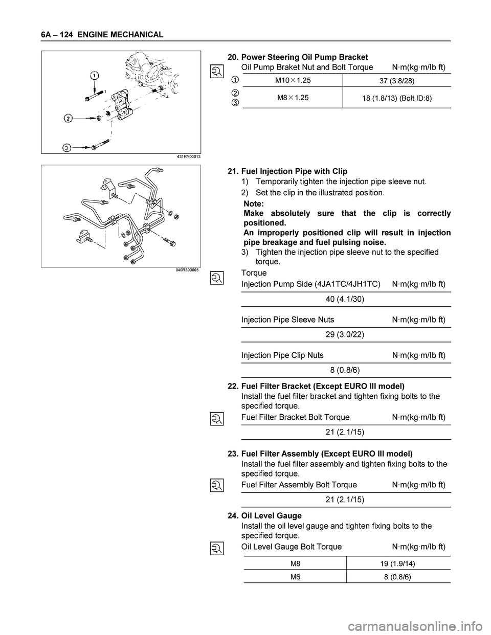
20. Power Steering Oil Pump Bracket
Oil Pump Braket Nut and Bolt Torque N·m(kg·m/Ib ft)
1M10�1.25
37 (3.8/28)
2
3M8�1.25
18 (1.8/13) (Bolt ID:8)
040R300005
21. Fuel Injection Pipe with Clip
1) Temporarily tighten the injection pipe sleeve nut.
2) Set the clip in the illustrated position.
Note:
Make absolutely sure that the clip is correctly
positioned.
An improperly positioned clip will result in injection
pipe breakage and fuel pulsing noise.
3) Tighten the injection pipe sleeve nut to the specified
torque.
Torque
Injection Pump Side (4JA1TC/4JH1TC) N·m(kg·m/Ib ft)
40 (4.1/30)
Injection Pipe Sleeve Nuts N·m(kg·m/Ib ft)
29 (3.0/22)
Injection Pipe Clip Nuts N·m(kg·m/Ib ft)
8 (0.8/6)
22. Fuel Filter Bracket (Except EURO III model)
Install the fuel filter bracket and tighten fixing bolts to the
specified torque.
Fuel Filter Bracket Bolt Torque N·m(kg·m/Ib ft)
21 (2.1/15)
23. Fuel Filter Assembly (Except EURO III model)
Install the fuel filter assembly and tighten fixing bolts to the
specified torque.
Fuel Filter Assembly Bolt Torque N·m(kg·m/Ib ft)
21 (2.1/15)
24. Oil Level Gauge
Install the oil level gauge and tighten fixing bolts to the
specified torque.
Oil Level Gauge Bolt Torque N·m(kg·m/Ib ft)
M8 19 (1.9/14)
M6 8 (0.8/6)
431RY00013
Page 1287 of 4264
ENGINE COOLING 6B – 7
DIAGNOSIS
Engine Cooling Trouble
Symptom Possible Cause Action
Low Engine Coolant level Replenish
Thermo meter unit faulty Replace
Faulty thermostat Replace
Faulty Engine Coolant temperature
sensor Repair or replace
Clogged radiator Clean or replace
Faulty radiator cap Replace
Low engine oil level or use of
improper engine oil Replenish or change oil
Clogged exhaust system Clean exhaust system or replace
faulty parts
Faulty Throttle Position sensor Replace throttle valve assembly
Open or shorted Throttle Position
sensor circuit Repair or replace
Engine overheating
Damaged cylinder head gasket Replace
Engine overcooling Faulty thermostat Replace
Faulty thermostat Replace Engine slow to warm–up
Thermo unit faulty Replace
Page 1288 of 4264
6B – 8 ENGINE COOLING
Draining and Refilling Cooling System
Before draining the cooling system, inspect the system and
perform any necessary service to ensure that it is clean, does
not leak and is in proper working order. The engine coolan
t
(EC) level should be between the “MIN" and “MAX" lines o
f
reserve tank when the engine is cold. If low, check for leakage
and add EC up to the “MAX" line.
There should not be any excessive deposit of rust or scales
around the radiator cap or radiator filler hole, and the EC
should also be free from oil.
Replace the EC if excessively dirty.
P1010064
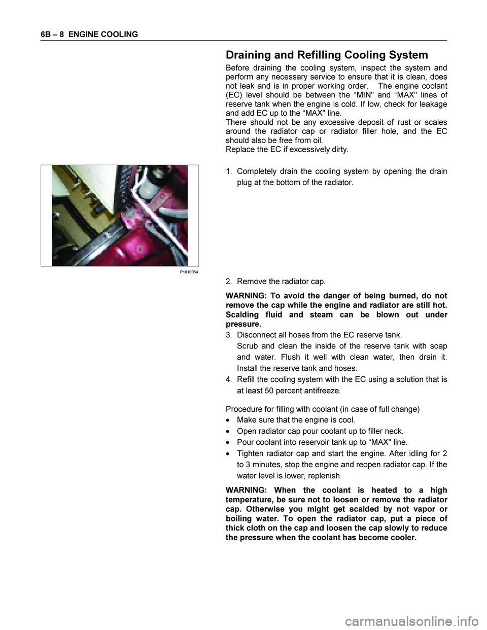
1. Completely drain the cooling system by opening the drain
plug at the bottom of the radiator.
2. Remove the radiator cap.
WARNING: To avoid the danger of being burned, do not
remove the cap while the engine and radiator are still hot.
Scalding fluid and steam can be blown out unde
r
pressure.
3. Disconnect all hoses from the EC reserve tank.
Scrub and clean the inside of the reserve tank with soap and water. Flush it well with clean water, then drain it.
Install the reserve tank and hoses.
4. Refill the cooling system with the EC using a solution that is at least 50 percent antifreeze.
Procedure for filling with coolant (in case of full change)
� Make sure that the engine is cool.
� Open radiator cap pour coolant up to filler neck.
� Pour coolant into reservoir tank up to “MAX" line.
� Tighten radiator cap and start the engine. After idling for 2
to 3 minutes, stop the engine and reopen radiator cap. If the
water level is lower, replenish.
WARNING: When the coolant is heated to a high
temperature, be sure not to loosen or remove the radiato
r
cap. Otherwise you might get scalded by not vapor or
boiling water. To open the radiator cap, put a piece of
thick cloth on the cap and loosen the cap slowly to reduce
the pressure when the coolant has become cooler.
Page 1320 of 4264
6C – 20 FUEL SYSTEM
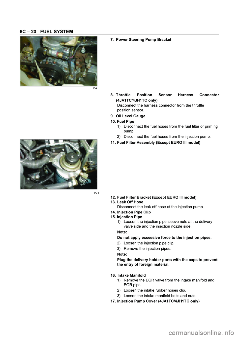
7. Power Steering Pump Bracket
6C-4 8. Throttle Position Sensor Harness Connector
(4JA1TC/4JH1TC only)
Disconnect the harness connector from the throttle
position sensor.
9. Oil Level Gauge
10. Fuel Pipe
1) Disconnect the fuel hoses from the fuel filter or priming
pump.
2) Disconnect the fuel hoses from the injection pump.
11. Fuel Filter Assembly (Except EURO III model)
6C-5
12. Fuel Filter Bracket (Except EURO III model)
13. Leak Off Hose
Disconnect the leak off hose at the injection pump.
14. Injection Pipe Clip
15. Injection Pipe
1) Loosen the injection pipe sleeve nuts at the delivery
valve side and the injection nozzle side.
Note:
Do not apply excessive force to the injection pipes.
2) Loosen the injection pipe clip.
3) Remove the injection pipes.
Note:
Plug the delivery holder ports with the caps to prevent
the entry of foreign material.
16. Intake Manifold
1) Remove the EGR valve from the intake manifold and
EGR pipe.
2) Loosen the intake rubber hoses clip.
3) Loosen the intake manifold bolts and nuts.
17. Injection Pump Cover (4JA1TC/4JH1TC only)
Page 1324 of 4264
6C – 24 FUEL SYSTEM
6. Injection Pipe
Install the injection pipe.
Injection Pipe Torque N·m(kg·m / lb ft)
29 (3.0 / 22)
Nozzle Side (4JA1TC/4JH1TC) N·m(kg·m / lb ft)
29 (3.0 / 22)
Pump Side (4JA1TC/4JH1TC) N·m(kg·m / lb ft)
40 (4.1 / 30)
7. Injection Pipe Clip
Install the injection pipe clip.
Note:
Make absolutely sure that the clip is correctly
positioned.
Injection Pipe Clip Torque N·m(kg·m / lb in)
8 (0.8 / 69)
8. Leak Off Pipe and Leak Off Hose
Install the leak off pipe to injection nozzle and connect the
leak off hose to the injection pump.
9. Fuel Filter Bracket (Except EURO III model)
Install the fuel filter bracket and tighten bolts to the
specified torque.
Fuel Filter Bracket Bolts Torque N·m(kg·m / lb ft)
21 (2.1 / 15)
10. Fuel Filter Assembly (Except EURO III model)
Install the fuel filter assembly to bracket and tighten bolts
to the specified torque.
Fuel Filter Assembly Bolts
Torque N·m(kg·m / lb ft)
21 (2.1 / 15)
11. Fuel Pipe
1) Connect the fuel hoses to the fuel filter or priming
pump.
2) Connect the fuel hoses to the injection pump.
12. Oil Level Gauge
Install the oil level gauge and tighten bolts to the specified
torque.
Oil Level Gauge Bolts
Torque N·m(kg·m / lb ft)
M8: 19 (1.9 / 14)
M6: 8 (0.8/6 lb in)
Page 1353 of 4264
ENGINE ELECTRICAL 6D – 15
Oil seal
The oil seal must be replaced with a new one whenever
the alternator is disassembled.
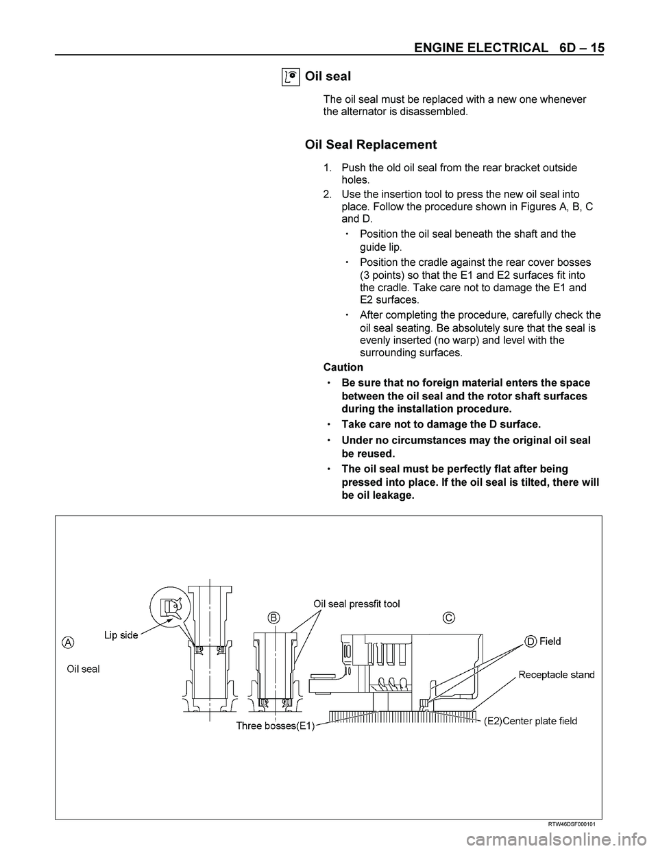
Oil Seal Replacement
1. Push the old oil seal from the rear bracket outside
holes.
2. Use the insertion tool to press the new oil seal into
place. Follow the procedure shown in Figures A, B, C
and D.
� Position the oil seal beneath the shaft and the
guide lip.
� Position the cradle against the rear cover bosses
(3 points) so that the E1 and E2 surfaces fit into
the cradle. Take care not to damage the E1 and
E2 surfaces.
� After completing the procedure, carefully check the
oil seal seating. Be absolutely sure that the seal is
evenly inserted (no warp) and level with the
surrounding surfaces.
Caution
�
�� � Be sure that no foreign material enters the space
between the oil seal and the rotor shaft surfaces
during the installation procedure.
�
�� � Take care not to damage the D surface.
�
�� � Under no circumstances may the original oil seal
be reused.
�
�� � The oil seal must be perfectly flat after being
pressed into place. If the oil seal is tilted, there will
be oil leakage.
RTW46DSF000101