2004 ISUZU TF SERIES circuit diagram
[x] Cancel search: circuit diagramPage 3 of 4264
ACCESSORIES 9-1
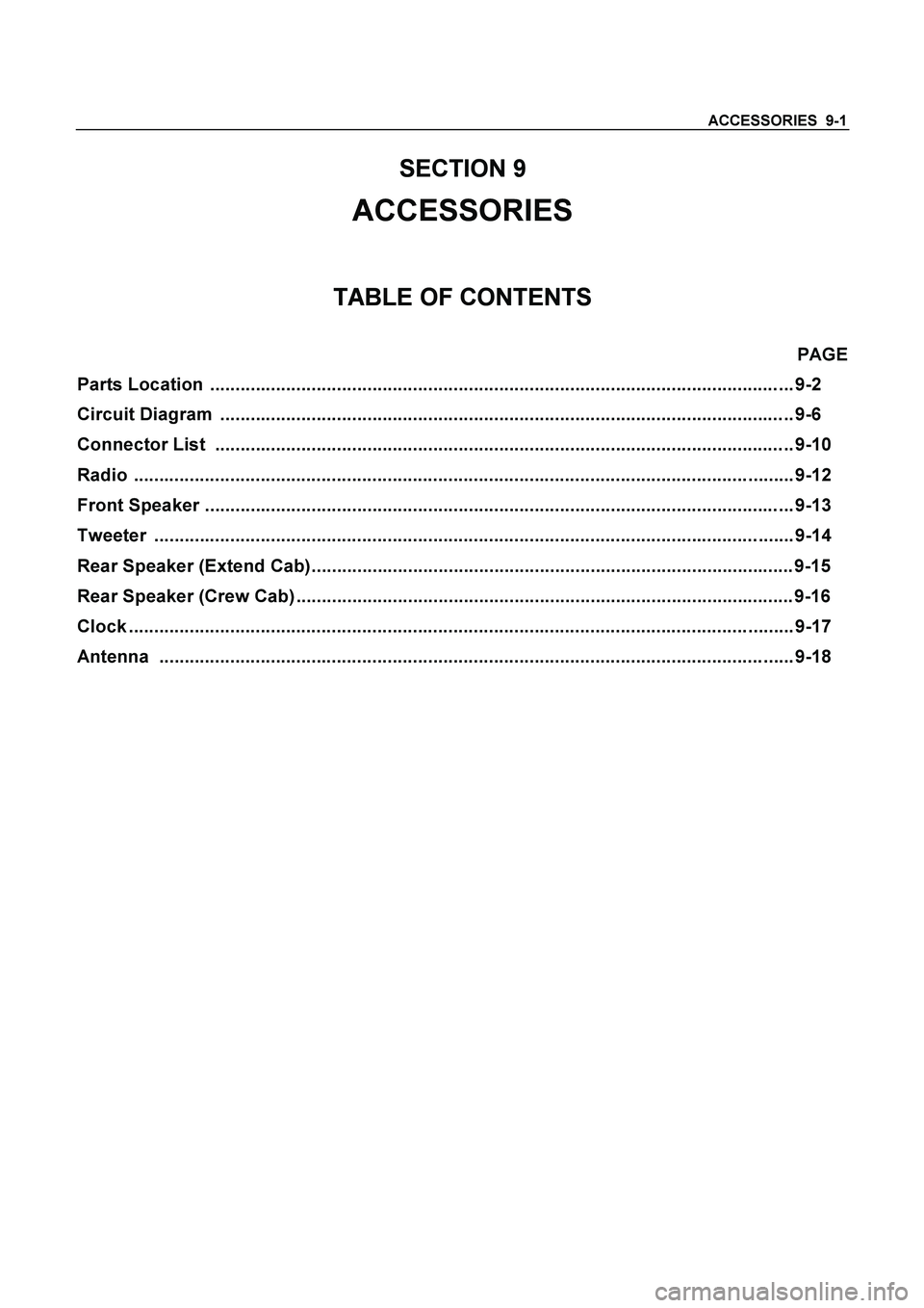
SECTION 9
ACCESSORIES
TABLE OF CONTENTS
PAGE
Parts Location ................................................................................................................... 9-2
Circuit Diagram ................................................................................................................. 9-6
Connector List .................................................................................................................. 9-10
Radio .................................................................................................................................. 9-12
Front Speaker .................................................................................................................... 9-13
Tweeter .............................................................................................................................. 9-14
Rear Speaker (Extend Cab)............................................................................................... 9-15
Rear Speaker (Crew Cab) .................................................................................................. 9-16
Clock ................................................................................................................................... 9-17
Antenna ............................................................................................................................. 9-18
Page 8 of 4264
9-6 ACCESSORIES
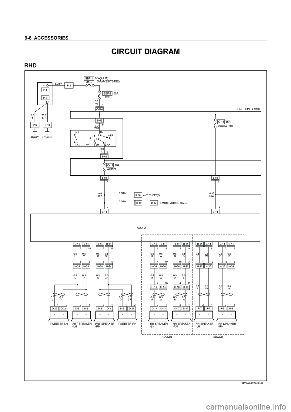
CIRCUIT DIAGRAM
RHD
RTW48AXF011101
Page 74 of 4264

9A1-4 RESTRAINT CONTROL SYSTEM
cautions in the service manual and on warning labels
attached to SRS components.
Basic Electrical Circuits
You should understand the basic theory of electricity
including series and parallel circuits, and understand
the voltage drops across series resistors. You should
know the meaning of voltage (volts), current (amps),
and resistance (ohms). You should understand what
happens in a circuit with an open or a shorted wire. You
should be able to read and understand a wiring
diagram.
“Flash Code” Diagnostics
Flash code diagnostics can be used to read active
codes and to determine if history codes are present but
cannot be used to clear codes or read history codes.
Flash code diagnostics is enabled by grounding by
terminal 4 shorting to terminal 13 of the DLC connector
with the ignition switch “ON”. Grounding terminal 4 of
the DLC connector pulls the “Diagnostics Request”
input (Terminal 1) of the SRS control unit low and
signals the SRS control unit to enter the flash code
diagnostic display mode.
060R300052
Page 317 of 4264
BRAKE CONTROL SYSTEM 5A-1
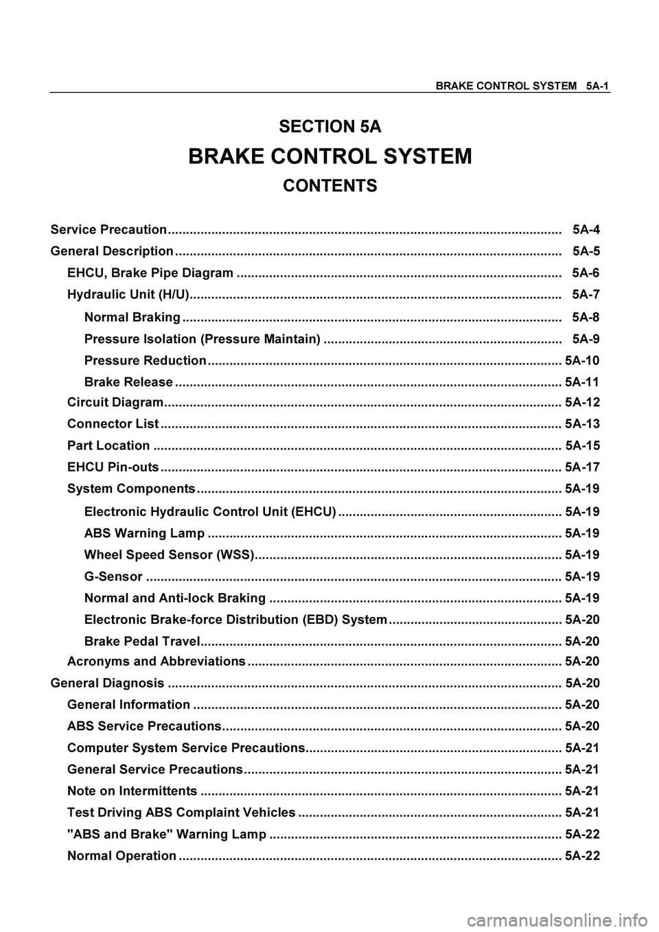
SECTION 5A
BRAKE CONTROL SYSTEM
CONTENTS
Service Precaution ............................................................................................................. 5A-4
General Description ........................................................................................................... 5A-5
EHCU, Brake Pipe Diagram .......................................................................................... 5A-6
Hydraulic Unit (H/U)....................................................................................................... 5A-7
Normal Braking ......................................................................................................... 5A-8
Pressure Isolation (Pressure Maintain) .................................................................. 5A-9
Pressure Reduction .................................................................................................. 5A-10
Brake Release ........................................................................................................... 5A-11
Circuit Diagram.............................................................................................................. 5A-12
Connector List ............................................................................................................... 5A-13
Part Location ................................................................................................................. 5A-15
EHCU Pin-outs ............................................................................................................... 5A-17
System Components ..................................................................................................... 5A-19
Electronic Hydraulic Control Unit (EHCU) .............................................................. 5A-19
ABS Warning Lamp .................................................................................................. 5A-19
Wheel Speed Sensor (WSS)..................................................................................... 5A-19
G-Sensor ................................................................................................................... 5A-19
Normal and Anti-lock Braking ................................................................................. 5A-19
Electronic Brake-force Distribution (EBD) System ................................................ 5A-20
Brake Pedal Travel.................................................................................................... 5A-20
Acronyms and Abbreviations ....................................................................................... 5A-20
General Diagnosis ............................................................................................................. 5A-20
General Information ...................................................................................................... 5A-20
ABS Service Precautions.............................................................................................. 5A-20
Computer System Service Precautions....................................................................... 5A-21
General Service Precautions........................................................................................ 5A-21
Note on Intermittents .................................................................................................... 5A-21
Test Driving ABS Complaint Vehicles ......................................................................... 5A-21
"ABS and Brake" Warning Lamp ................................................................................. 5A-22
Normal Operation .......................................................................................................... 5A-22
Page 328 of 4264
5A-12 BRAKE CONTROL SYSTEM
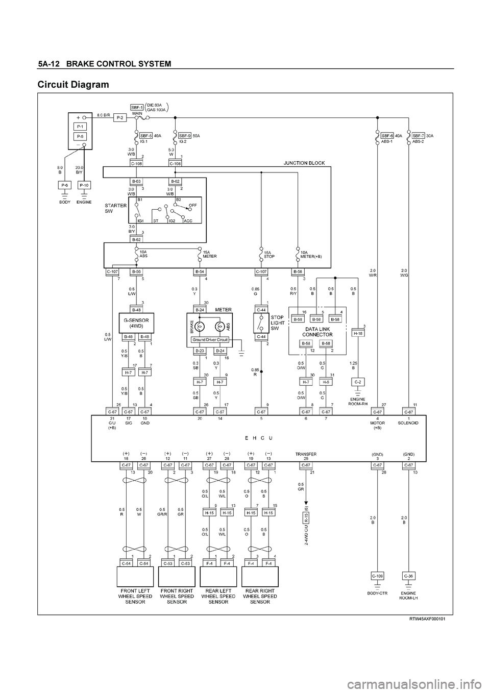
Circuit Diagram
RTW45AXF000101
Page 659 of 4264
ELECTRICAL-BODY AND CHASSIS 8A-1
SECTION 8A
ELECTRICAL-BODY AND CHASSIS
TABLE OF CONTENTS
PAGE
General Information ........................................................................................................ 8A- 4
Notes for Working on Electrical Items .......................................................................... 8A- 5
Symbols and Abbreviations ........................................................................................... 8A- 11
Symbols ...................................................................................................................... 8A- 11
Abbreviations ............................................................................................................. 8A- 12
Parts for Electrical Circuit .............................................................................................. 8A- 13
Wiring .......................................................................................................................... 8A- 13
Fuse ............................................................................................................................. 8A- 15
Fusible Link ................................................................................................................ 8A- 15
Relay ............................................................................................................................ 8A- 16
Diode ........................................................................................................................... 8A- 17
Connector ................................................................................................................... 8A- 18
Battery ......................................................................................................................... 8A- 19
Reading the Circuit Diagram .......................................................................................... 8A- 22
Parts Location ............................................................................................................ 8A- 22
Circuit Diagram ........................................................................................................... 8A- 23
Connector List ............................................................................................................. 8A- 23
Main Data and Specifications ........................................................................................ 8A- 24
Bulb Specifications .................................................................................................... 8A- 24
Relay and Fuse ................................................................................................................ 8A- 26
Relay and Fuse Box Location ................................................................................... 8A- 26
Relay Location ............................................................................................................ 8A- 28
Page 662 of 4264
8A-4 ELECTRICAL-BODY AND CHASSIS
GENERAL INFORMATION
The body and chassis electrical system operates on a twelve volt power supply with negative ground polarity.
The main harness consists of the engine harness, the instrument harness, the body harness, and the chassis
harness.
The harnesses use a split corrugated tube to protect the wires from the elements.
Wire size is determined by current flow, circuit length, and voltage drop.
All wires have color-coded insulation.
Wire color-codes are shown in the circuit diagrams.
This makes it easier to trace circuits and to make the proper connections.
Each circuit consists of the following:
1. Power source - The battery and the alternator
2. Wires - To carry electrical current through the circuit
3. Fuses - To protect the circuit against current overload
4. Relays - To protect voltage drop between the battery and the circuit parts and to protect the switch points against
burning
5. Switches - To open and close the circuit
6. Load - Any device, such as a light or motor, which converts the electrical current into useful work
7. Ground - To allow the current to flow back to the power source
Page 671 of 4264

ELECTRICAL-BODY AND CHASSIS 8A-13
PARTS FOR ELECTRICAL CIRCUIT
WIRING
Wire Color
All wires have color-coded insulation.
Wires belonging to system's main harness will have a single
color.
Wires belonging to a system's sub-circuits will have a colored
stripe.
Striped wires use the following code to show wire size and
colors.
Example: 0.5 G
/ R
Red (Stripe color)
Green (Base color)
Wire size (0.5mm
2)
Abbreviations are used to indicate wire color within a circuit
diagram.
Refer to the following table.
Wire Color-Coding
Color-Coding Meaning Color-Coding Meaning
B Black BR Brown
W White LG Light green
R Red GR Grey
G Green P Pink
Y Yellow LB Light blue
L Blue V Violet
O Orange