2004 ISUZU TF SERIES jump cable
[x] Cancel search: jump cablePage 337 of 4264

BRAKE CONTROL SYSTEM 5A-21
Computer System Service Precautions
The Anti-lock Brake System and Electronic Brake-force
Distribution interfaces directly with the Electronic
Hydraulic Control Unit (EHCU) which is a control
computer that is similar in some regards to the Engine
Control Module. These modules are designed to
withstand normal current draws associated with vehicle
operation. However, care must be taken to avoid
overloading any of the EHCU circuits. In testing for
opens or shorts, do not ground or apply voltage to any
of the circuits unless instructed to do so by the
appropriate diagnostic procedure. These circuits should
only be tested with a high impedance multimeter
5-8840-0366-0 or special tools as described in this
section. Power should never be removed or applied to
any control module with the ignition in the “ON”
position.
Before removing or connecting battery cables, fuses or
connectors, always turn the ignition switch to the “OFF”
position.
General Service Precautions
The following are general precautions which should be
observed when servicing and diagnosing the Anti-lock
Brake System and/or other vehicle systems. Failure to
observe these precautions may result in Anti-lock Brake
System and Electronic Brake-force Distribution
damage.
If welding work is to be performed on the vehicle
using an electric arc welder, the EHCU and valve
block connectors should be disconnected before
the welding operation begins.
The EHCU and valve block connectors should
never be connected or disconnected with the
ignition “ON”.
Note:
If only rear wheels are rotated using jacks or drum
tester, the system will diagnose a speed sensor
malfunction and the “ABS and Brake” warning lamp
will illuminate. But actually no trouble exists. When
the DTC is not detected and the ABS and BRAKE
warning lamp is on, “How to erase code” is
performed and a ABS and BRAKE warning lamp
are off.
If the battery has been discharged
The engine may stall if the battery has been completely
discharged and the engine is started via jumper cables.
This is because the Anti-lock Brake System (ABS) and
Electronic Brake-force Distribution (EBD) System
requires a large quantity of electricity. In this case, wait
until the battery is recharged, or set the ABS and EBD
to a non-operative state by removing the fuse for the
ABS. After the battery has been recharged, stop the
engine and install the ABS fuse. Start the engine again,
and confirm that the ABS warning Lamp does not light.
Note on Intermittents
As with virtually any electronic system, it is difficult to
identify an intermittent failure. In such a case
duplicating the system malfunction during a test drive or
a good description of vehicle behavior from the
customer may be helpful in locating a “most likely”
failed component or circuit. The symptom diagnosis
chart may also be useful in isolating the failure. Most
intermittent problems are caused by faulty electrical
connections or wiring. When an intermittent failure is
encountered, check suspect circuits for:
Suspected harness damage.
Poor mating of connector halves or terminals not
fully seated in the connector body (backed out).
Improperly formed or damaged terminals.
Test Driving ABS Complaint Vehicles
In case that there has been an abnormality in the
lighting pattern of “ABS” warning lamp, the fault can be
located in accordance with the “DIAGNOSIS BY “ABS”
WARNING LAMP ILLUMINATION PATTERN”. In case
of such trouble as can be detected by the driver as a
vehicle symptom, however, it is necessary to give a test
drive following the test procedure mentioned below,
thereby reproducing the symptom for trouble diagnosis
on a symptom basis:
1.
Start the engine and make sure that the “ABS” W/L
goes OFF. If the W/L remains ON, it means that
the Diagnostic Trouble Code (DTC) is stored.
Therefore, read the code and locate the fault.
Note: The DTC cannot be cleared if the vehicle speed
does not exceed about 6km/h (4mph) at DTC, even
though the repair operation is completed.
2. Start the vehicle and accelerate to about 30 km/h
(19 mph) or more.
3. Slowly brake and stop the vehicle completely.
4. Then restart the vehicle and accelerate to about 40
km/h (25 mph) or more.
5. Brake at a time so as to actuate the ABS and stop
the vehicle.
6. Be cautious of abnormality during the test. If the
W/L is actuated while driving, read the DTC and
locate the fault.
7. If the abnormality is not reproduced by the test,
make best efforts to reproduce the situation
reported by the customer.
8. If the abnormality has been detected, repair in
accordance with the “SYMPTOM DIAGNOSIS” .
Note:
Be sure to give a test drive on a wide, even road
with a small traffic.
If an abnormality is detected, be sure to suspend
the test and start trouble diagnosis at once.
Page 509 of 4264

CAB 10-1
SECTION 10
CAB
TABLE OF CONTENTS
PAGE
Windshield.......................................................................................................................... 10- 2
Rear Window Assembly .................................................................................................... 10- 7
Front Door Assembly ........................................................................................................ 10- 10
Rear Door Assembly (Crew Cab) ...................................................................................... 10- 20
Instrument Panel................................................................................................................ 10- 28
Floor Console..................................................................................................................... 10- 34
Console Box (Without Floor Console) ............................................................................. 10- 38
Headlining .......................................................................................................................... 10- 39
Interior Trim Panels ...........................................................................................................10- 44
Fuel Filler Lid Opener Lever/Cable................................................................................... 10- 55
Quarter Glass (Extend Cab) .............................................................................................. 10- 70
Font Seat ............................................................................................................................ 10- 71
Rear Seat (Crew Cab) ........................................................................................................ 10- 74
Jump Seat (Extend Cab) ................................................................................................... 10- 75
Front Seat Belt ................................................................................................................... 10- 76
Rear Seat Belt (Crew Cab) ................................................................................................ 10- 80
Rear Seat Belt (Extend Cab) ............................................................................................. 10- 84
Front Wheel Extension ...................................................................................................... 10- 87
Rear Wheel Extension ....................................................................................................... 10- 88
Tail Gate Assembly ............................................................................................................ 10- 89
Page 677 of 4264

ELECTRICAL-BODY AND CHASSIS 8A-19
Battery-1
BATTERY
Inspection
1. Check the battery terminals 1 for corrosion.
2. Check the battery cables
2 for looseness.
3. Check the battery case
3 for cracks and other damage.
4. Check the battery electrolyte level.
Battery-2
Battery Replacement
1. Disconnect the battery ground cable 1.
2. Disconnect the battery positive cable
2.
3. Remove the battery clamp
3.
4. Remove the battery
Caution:
It is important that the battery ground cable be removed
first.
Removing the battery positive cable first can result in a
short circuit.
Jump Starting the Engine with a Booster Battery
The following description assumes that you are using a booster
battery mounted on a second vehicle.
The listed steps (with some minor modifications) are also
applicable if you are using a naked booster battery or special
battery charging equipment.
Page 678 of 4264

8A-20 ELECTRICAL-BODY AND CHASSIS
Caution:
Never push or tow the vehicle in an attempt to start it.
Extensive damage to the emission system and other
vehicle parts will result.
(Only catalytic converter vehicle)
Treat both the discharged battery and the booster battery
with great care when using jumper cables.
Carefully follow the procedure outlined below.
Always be aware of the dangers of sparking.
Failure to follow the following procedure can result in:
a. Serious personal injury, specially to your eyes.
b. Extensive property damage from a battery explosion,
battery acid discharge, or electrical file.
c. Extensive damage to the electronic components o
f
both vehicles.
Do not use a 24 volt booster battery.
Serious damage to the vehicle's electrical system and
electronic components will result.
Jump Starting Procedure
1. Set the parking brake on both vehicles.
2. If one or both vehicles is equipped with a manual
transmission, place the gear shift in the "NEUTRAL"
position.
3. Turn off the ignition on both vehicles.
4. Turn off all vehicle lights and accessories.
5 Be sure that the two vehicles are not touching.
Attach the end of one jumper cable to the booster battery
positive terminal.
6
Attach the other end of the same cable to the discharged
battery positive terminal.
7. Once again, check that the booster battery has a 12 vol
t
rating.
8.
Attach one end of the remaining booster cable to the
booster battery negative terminal.
9.
Attach the other end of the booster cable to a solid ground
(such as the air conditioner compressor mounting bracke
t
or the alternator mounting bracket) in the engine room o
f
the vehicle with the discharged battery.
Be sure that the ground connection is at least 500 mm (20
in) from the discharged battery.
Page 679 of 4264

ELECTRICAL-BODY AND CHASSIS 8A-21
Caution:
Do not attach the booster cable to the discharged battery
negative terminal.
11. Start the engine of the vehicle with the booster battery.
Check that all unnecessary electrical accessories are off.
12. Start the engine of the vehicle with the discharged battery.
13. Remove the jumper cables in the reverse order to which
they were attached.
Caution:
Be absolutely sure to remove the negative jumper cable
from the vehicle with the discharged battery first.
Page 1493 of 4264

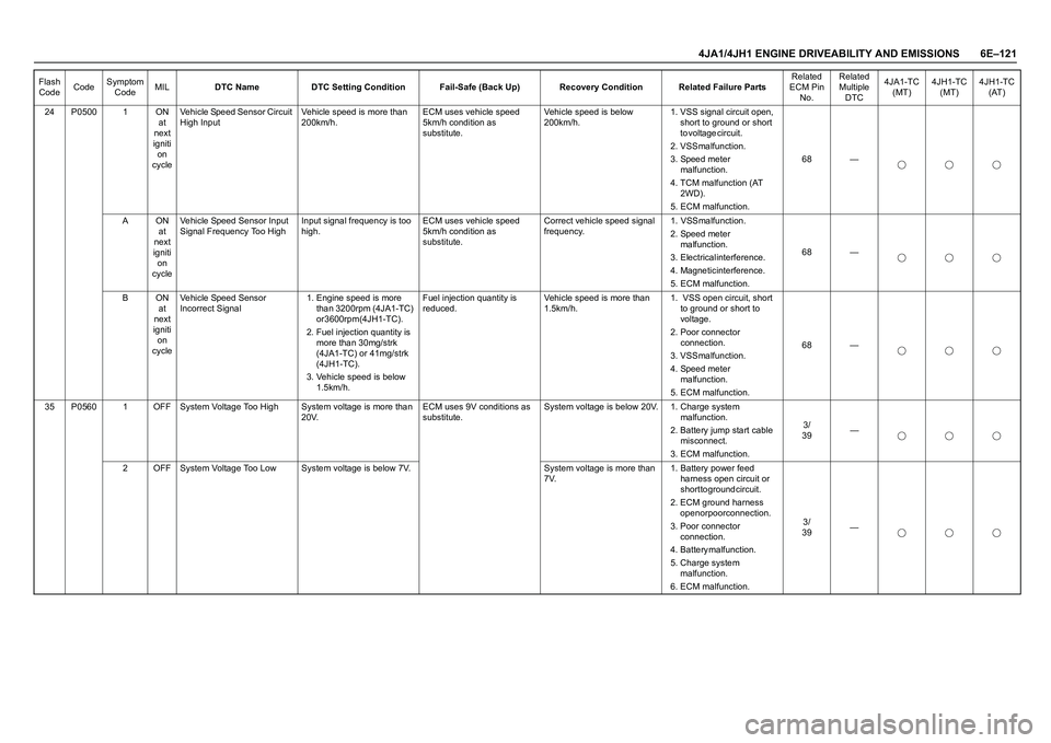
4JA1/4JH1 ENGINE DRIVEABILITY AND EMISSIONS 6E–121
24 P0500 1 ON
at
next
igniti
on
cycleVehicle Speed Sensor Circuit
High InputVehicle speed is more than
200km/h.ECM uses vehicle speed
5km/h condition as
substitute.Vehicle speed is below
200km/h.1. VSS signal circuit open,
short to ground or short
t o v o l t a g e c i r c u i t .
2. VSS malfunction.
3. Speed meter
m a l f u n c t i o n .
4. TCM malfunction (AT
2 W D ) .
5. ECM malfunction.68 —
A O N
at
next
igniti
on
cycleVehicle Speed Sensor Input
Signal Frequency Too HighInput signal frequency is too
high.ECM uses vehicle speed
5km/h condition as
substitute.Correct vehicle speed signal
frequency. 1. VSS malfunction.
2. Speed meter
m a l f u n c t i o n .
3. Electrical interference.
4. Magnetic interference.
5. ECM malfunction.68 —
B O N
at
next
igniti
on
cycleVehicle Speed Sensor
Incorrect Signal1. Engine speed is more
than 3200rpm (4JA1-TC)
or 3600rpm (4JH1-TC).
2. Fuel injection quantity is
more than 30mg/strk
(4JA1-TC) or 41mg/strk
( 4 J H 1 - T C ) .
3. Vehicle speed is below
1.5km/h.Fuel injection quantity is
reduced.Vehicle speed is more than
1.5km/h.1. VSS open circuit, short
to ground or short to
voltage.
2. Poor connector
c o n n e c t i o n .
3. VSS malfunction.
4. Speed meter
m a l f u n c t i o n .
5. ECM malfunction.68 —
35 P0560 1 OFF System Voltage Too High System voltage is more than
20V.ECM uses 9V conditions as
substitute.System voltage is below 20V. 1. Charge system
m a l f u n c t i o n .
2. Battery jump start cable
misconnect.
3. ECM malfunction.3 /
39—
2 OFF System Voltage Too Low System voltage is below 7V. System voltage is more than
7V.1. Battery power feed
harness open circuit or
short to ground circuit.
2. ECM ground harness
open or poor connection.
3. Poor connector
c o n n e c t i o n .
4 . B a t t e r y m a l f u n c t i o n .
5. Charge system
m a l f u n c t i o n .
6. ECM malfunction.3 /
39— Flash
CodeCodeSymptom
CodeMILDTC Name DTC Setting Condition Fail-Safe (Back Up) Recovery Condition Related Failure PartsRelated
ECM Pin
No.Related
Multiple
DTC4JA1-TC
(MT)4JH1-TC
(MT)4JH1-TC
(AT)
Page 1494 of 4264

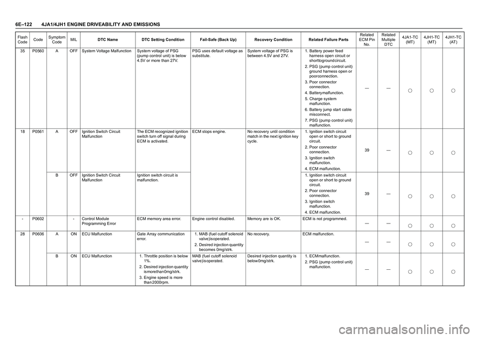
6E–122 4JA1/4JH1 ENGINE DRIVEABILITY AND EMISSIONS
35 P0560 A OFF System Voltage Malfunction System voltage of PSG
(pump control unit) is below
4.5V or more than 27V.PSG uses default voltage as
substitute.System voltage of PSG is
between 4.5V and 27V.1. Battery power feed
harness open circuit or
short to ground circuit.
2. PSG (pump control unit)
ground harness open or
p o o r c o n n e c t i o n .
3. Poor connector
c o n n e c t i o n .
4 . B a t t e r y m a l f u n c t i o n .
5. Charge system
m a l f u n c t i o n .
6. Battery jump start cable
misconnect.
7. PSG (pump control unit)
malfunction.——
18 P0561 A OFF Ignition Switch Circuit
MalfunctionThe ECM recognized ignition
switch turn off signal during
ECM is activated.ECM stops engine. No recovery until condition
match in the next ignition key
cycle.1. Ignition switch circuit
open or short to ground
c i r c u i t .
2. Poor connector
c o n n e c t i o n .
3. Ignition switch
m a l f u n c t i o n .
4. ECM malfunction.39 —
B OFF Ignition Switch Circuit
MalfunctionIgnition switch circuit is
malfunction.1. Ignition switch circuit
open or short to ground
c i r c u i t .
2. Poor connector
c o n n e c t i o n .
3. Ignition switch
m a l f u n c t i o n .
4. ECM malfunction.39 —
- P0602 - Control Module
Programming ErrorECM memory area error. Engine control disabled. Memory are is OK. ECM is not programmed.
——
28 P0606 A ON ECU Malfunction Gate Array communication
error.1. MAB (fuel cutoff solenoid
v a l v e ) i s o p e r a t e d .
2. Desired injection quantity
becomes 0mg/strk.No recovery. ECM malfunction.
——
B ON ECU Malfunction 1. Throttle position is below
1 % .
2. Desired injection quantity
is more than 0mg/strk.
3. Engine speed is more
t h a n 2 0 0 0 r p m . MAB (fuel cutoff solenoid
v a l v e ) i s o p e r a t e d . Desired injection quantity is
b e l o w 0 m g / s t r k . 1 . E C M m a l f u n c t i o n .
2. PSG (pump control unit)
malfunction.
—— Flash
CodeCodeSymptom
CodeMILDTC Name DTC Setting Condition Fail-Safe (Back Up) Recovery Condition Related Failure PartsRelated
ECM Pin
No.Related
Multiple
DTC4JA1-TC
(MT)4JH1-TC
(MT)4JH1-TC
(AT)
Page 1626 of 4264

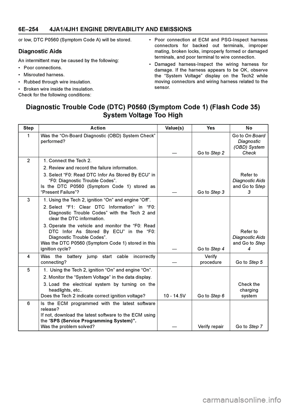
6E–254 4JA1/4JH1 ENGINE DRIVEABILITY AND EMISSIONS
or low, DTC P0560 (Symptom Code A) will be stored.
Diagnostic Aids
An intermittent may be caused by the following:
Poor connections.
Misrouted harness.
Rubbed through wire insulation.
Broken wire inside the insulation.
Check for the following conditions:Poor connection at ECM and PSG-Inspect harness
connectors for backed out terminals, improper
mating, broken locks, improperly formed or damaged
terminals, and poor terminal to wire connection.
Damaged harness-Inspect the wiring harness for
damage. If the harness appears to be OK, observe
the “System Voltage” display on the Tech2 while
moving connectors and wiring harness related to the
sensor.
Diagnostic Trouble Code (DTC) P0560 (Symptom Code 1) (Flash Code 35)
System Voltage Too High
Step Action Value(s) Yes No
1Was the “On-Board Diagnostic (OBD) System Check”
performed?
—Go to Step 2Go to On Board
Diagnostic
(OBD) System
Check
2 1. Connect the Tech 2.
2. Review and record the failure information.
3. Select “F0: Read DTC Infor As Stored By ECU” in
“F0: Diagnostic Trouble Codes”.
Is the DTC P0560 (Symptom Code 1) stored as
“Present Failure”?—Go to Step 3Refer to
Diagnostic Aids
and Go to Step
3
3 1. Using the Tech 2, ignition “On” and engine “Off”.
2. Select “F1: Clear DTC Information” in “F0:
Diagnostic Trouble Codes” with the Tech 2 and
clear the DTC information.
3. Operate the vehicle and monitor the “F0: Read
DTC Infor As Stored By ECU” in the “F0:
Diagnostic Trouble Codes”.
Was the DTC P0560 (Symptom Code 1) stored in this
ignition cycle?—Go to Step 4Refer to
Diagnostic Aids
and Go to Step
4
4 Was the battery jump start cable incorrectly
connecting?—Verify
procedure Go to Step 5
5 1. Using the Tech 2, ignition “On” and engine “On”.
2. Monitor the “System Voltage” in the data display.
3. Load the electrical system by turning on the
headlights, etc..
Does the Tech 2 indicate correct ignition voltage? 10 - 14.5V Go to Step 6Check the
charging
system
6 Is the ECM programmed with the latest software
release?
If not, download the latest software to the ECM using
the “SPS (Service Programming System)”.
Was the problem solved?—Verify repair Go to Step 7