Page 604 of 4264
7C-2 CLUTCH
MAIN DATA AND SPECIFICATIONS
ENGINE 6VE1
4JA1-T(L) 4JA1-TC
4JH1-TC C24SE
Clutch type Dry single plate with diaphragm
Size mm (in)260 (10.24) 225 (8.86) 250 (9.84) 240 (9.45)
Clamping force kg(lb)735 (1621) 500 (1103) 640 (1411) 560 (1235)
(N)(7200) (4900) (6300) (5500)
Pressure plate
Outside diameter mm(in)260 (10.24) 225 (8.86) 250 (9.84) 240 (9.45)
Inside diameter mm(in)170 (6.69) 150 (5.906) 160 (6.299) 160 (6.299)
Driven plate
Thickness mm(in)
at free 8.8 (0.346) 8.4 (0.331) 8.3 (0.327) 8.7 (0.342)
at compressed 8.2 (0.323) 7.8 (0.307) 7.8 (0.307) 8.0 (0.315)
Clutch Cont. type Hydraulic
Pedal free play mm(in)5.0-15.0 (0.2-0.6)
Master cylinder
Bore�
Stroke mm(in)15.87 �
35 (0.625 �
1.38)
Slave cylinder
Bore �
Stroke mm(in)22.22 �
18.9
(0.875 �
0.744) 19.05 �
23
(0.749 �
0.906) 20.64 �
23
(0.813 �
0.906) 19.05 �
23
(0.749 �
0.906)
Page 629 of 4264
CLUTCH 7C-27
201R300011
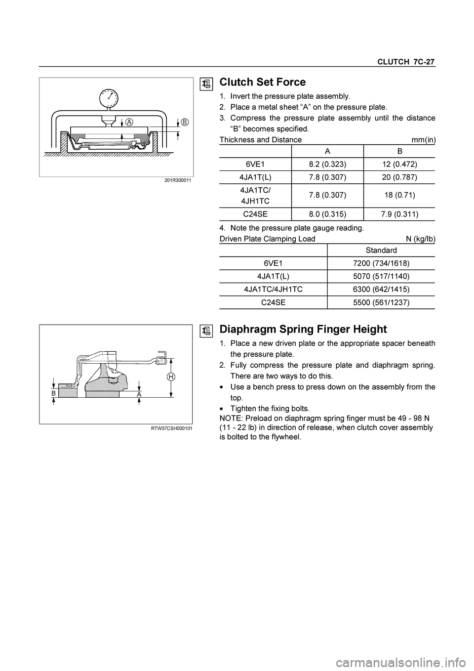
Clutch Set Force
1. Invert the pressure plate assembly.
2. Place a metal sheet “A” on the pressure plate.
3. Compress the pressure plate assembly until the distance
“B” becomes specified.
Thickness and Distance mm(in
)
A B
6VE1 8.2 (0.323) 12 (0.472)
4JA1T(L) 7.8 (0.307) 20 (0.787)
4JA1TC/
4JH1TC 7.8 (0.307) 18 (0.71)
C24SE 8.0 (0.315) 7.9 (0.311)
4. Note the pressure plate gauge reading.
Driven Plate Clamping Load N (kg/Ib)
Standard
6VE1 7200 (734/1618)
4JA1T(L) 5070 (517/1140)
4JA1TC/4JH1TC 6300 (642/1415)
C24SE 5500 (561/1237)
RTW37CSH000101
Diaphragm Spring Finger Height
1. Place a new driven plate or the appropriate spacer beneath
the pressure plate.
2. Fully compress the pressure plate and diaphragm spring.
There are two ways to do this.
�
Use a bench press to press down on the assembly from the
top.
� Tighten the fixing bolts.
NOTE: Preload on diaphragm spring finger must be 49 - 98 N
(11 - 22 lb) in direction of release, when clutch cover assembly
is bolted to the flywheel.
Page 630 of 4264
7C-28 CLUTCH
3. Measure the spring height from base to spring tip "H". If the
measured value exceeds the specified limit, the pressure
plate assembly must be replaced.
Spacer Thickness mm(in)
A B
6VE1 8.2 (0.323) 12 (0.472)
4JA1T(L) 7.8 (0.307) 20 (0.787)
4JA1TC/
4JH1TC 7.8 (0.307) 18 (0.71)
C24SE 8.0 (0.315) 7.9 (0.311)
Finger Height
6VE1 49.9-51.9 (1.96-2.04)
4JA1T(L) 31-33 (1.22-1.30)
4JA1TC/
4JH1TC 39-41 (1.54-1.61)
C24SE 39-41 (1.54-1.61)
Page 3144 of 4264
7B-26 MSG MODEL
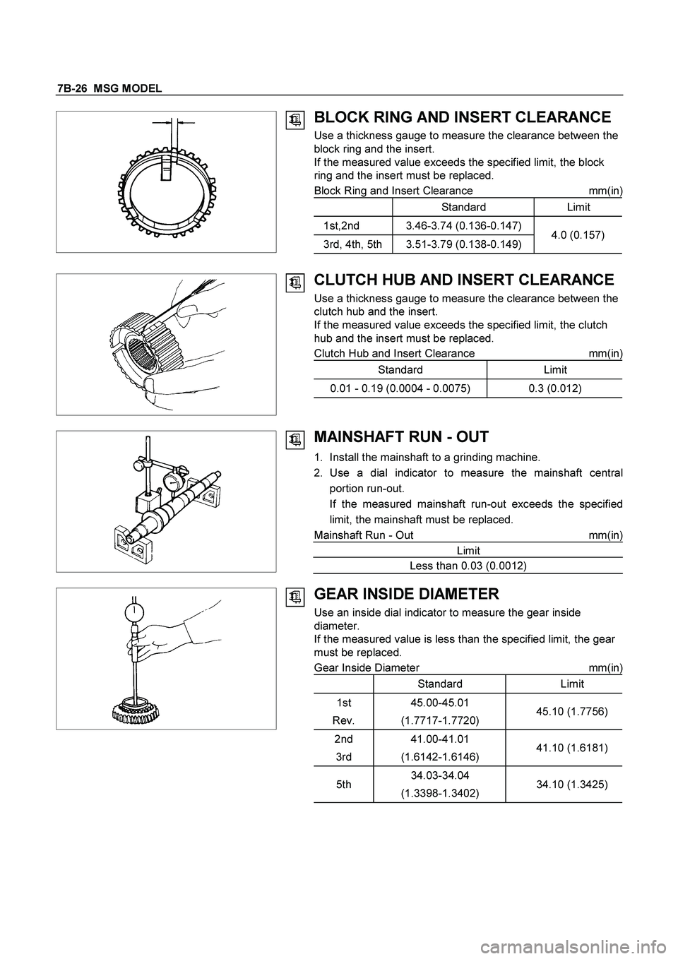
BLOCK RING AND INSERT CLEARANCE
Use a thickness gauge to measure the clearance between the
block ring and the insert.
If the measured value exceeds the specified limit, the block
ring and the insert must be replaced.
Block Ring and Insert Clearance mm(in)
Standard Limit
1st,2nd 3.46-3.74 (0.136-0.147)
3rd, 4th, 5th 3.51-3.79 (0.138-0.149)4.0 (0.157)
CLUTCH HUB AND INSERT CLEARANCE
Use a thickness gauge to measure the clearance between the
clutch hub and the insert.
If the measured value exceeds the specified limit, the clutch
hub and the insert must be replaced.
Clutch Hub and Insert Clearance mm(in)
Standard Limit
0.01 - 0.19 (0.0004 - 0.0075) 0.3 (0.012)
MAINSHAFT RUN - OUT
1. Install the mainshaft to a grinding machine.
2. Use a dial indicator to measure the mainshaft central
portion run-out.
If the measured mainshaft run-out exceeds the specified
limit, the mainshaft must be replaced.
Mainshaft Run - Out mm(in)
Limit
Less than 0.03 (0.0012)
GEAR INSIDE DIAMETER
Use an inside dial indicator to measure the gear inside
diameter.
If the measured value is less than the specified limit, the gear
must be replaced.
Gear Inside Diameter mm(in)
Standard Limit
1st
Rev.45.00-45.01
(1.7717-1.7720)45.10 (1.7756)
2nd
3rd41.00-41.01
(1.6142-1.6146)41.10 (1.6181)
5th34.03-34.04
(1.3398-1.3402)34.10 (1.3425)
Page 3150 of 4264
7B-32 MSG MODEL
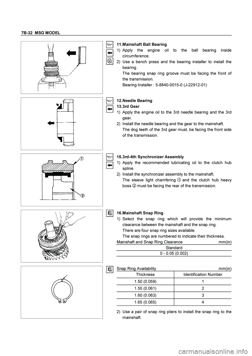
11. Mainshaft Ball Bearing
1) Apply the engine oil to the ball bearing inside
circumference.
2) Use a bench press and the bearing installer to install the
bearing.
The bearing snap ring groove must be facing the front o
f
the transmission.
Bearing Installer : 5-8840-0015-0 (J-22912-01)
12. Needle Bearing
13. 3rd Gear
1) Apply the engine oil to the 3rd needle bearing and the 3rd
gear.
2) Install the needle bearing and the gear to the mainshaft.
The dog teeth of the 3rd gear must, be facing the front side
of the transmission.
15. 3rd-4th Synchronizer Assembly
1)
Apply the recommended lubricating oil to the clutch hub
spline.
2) Install the synchronizer assembly to the mainshaft.
The sleeve light chamfering
1 and the clutch hub heavy
boss
2 must be facing the rear of the transmission.
16. Mainshaft Snap Ring
1) Select the snap ring which will provide the minimum
clearance between the mainshaft and the snap ring.
There are four snap ring sizes available.
The snap rings are numbered to indicate their thickness.
Mainshaft and Snap Ring Clearance mm(in)
Standard
0 - 0.05 (0.002)
Snap Ring Availability mm(in)Thickness Identification Number
1.50 (0.059) 1
1.55 (0.061) 2
1.60 (0.063) 3
1.65 (0.065) 4
2) Use a pair of snap ring pliers to install the snap ring to the
mainshaft.
Page 3154 of 4264
7B-36 MSG MODEL
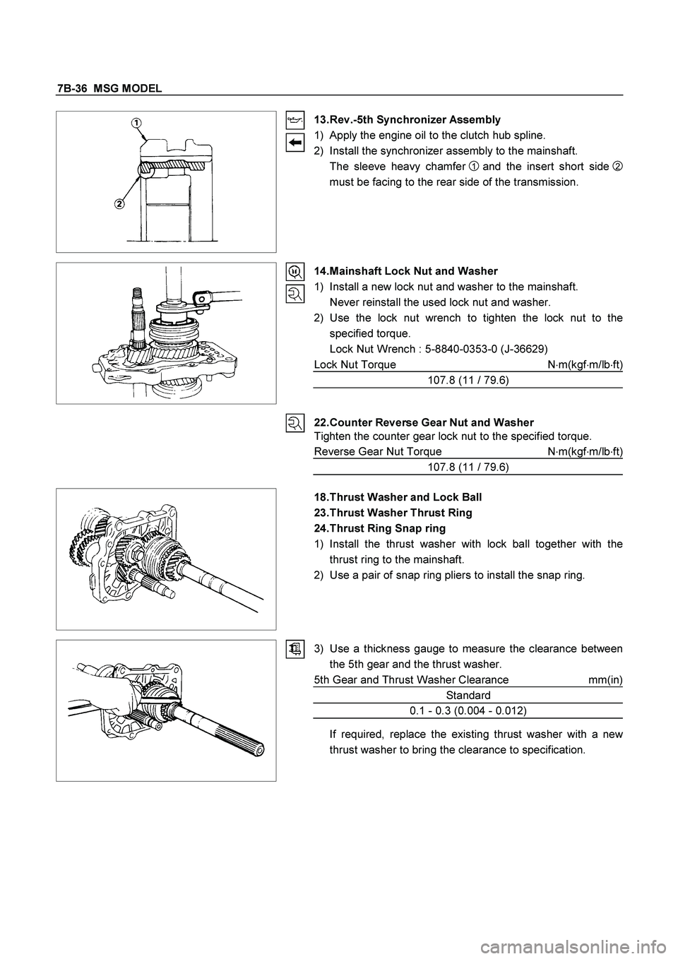
13. Rev.-5th Synchronizer Assembly
1) Apply the engine oil to the clutch hub spline.
2) Install the synchronizer assembly to the mainshaft.
The sleeve heavy chamfer
1 and the insert short side
2
must be facing to the rear side of the transmission.
14. Mainshaft Lock Nut and Washer
1) Install a new lock nut and washer to the mainshaft.
Never reinstall the used lock nut and washer.
2) Use the lock nut wrench to tighten the lock nut to the
specified torque.
Lock Nut Wrench : 5-8840-0353-0 (J-36629)
Lock Nut Torque N�m(kgf�m/lb�ft)
107.8 (11 / 79.6)
22. Counter Reverse Gear Nut and Washer
Tighten the counter gear lock nut to the specified torque.
Reverse Gear Nut Torque N�
m(kgf�
m/lb�
ft)
107.8 (11 / 79.6)
18. Thrust Washer and Lock Ball
23. Thrust Washer Thrust Ring
24. Thrust Ring Snap ring
1) Install the thrust washer with lock ball together with the
thrust ring to the mainshaft.
2) Use a pair of snap ring pliers to install the snap ring.
3) Use a thickness gauge to measure the clearance between
the 5th gear and the thrust washer.
5th Gear and Thrust Washer Clearance mm(in)
Standard
0.1 - 0.3 (0.004 - 0.012)
If required, replace the existing thrust washer with a new
thrust washer to bring the clearance to specification.
Page 3206 of 4264
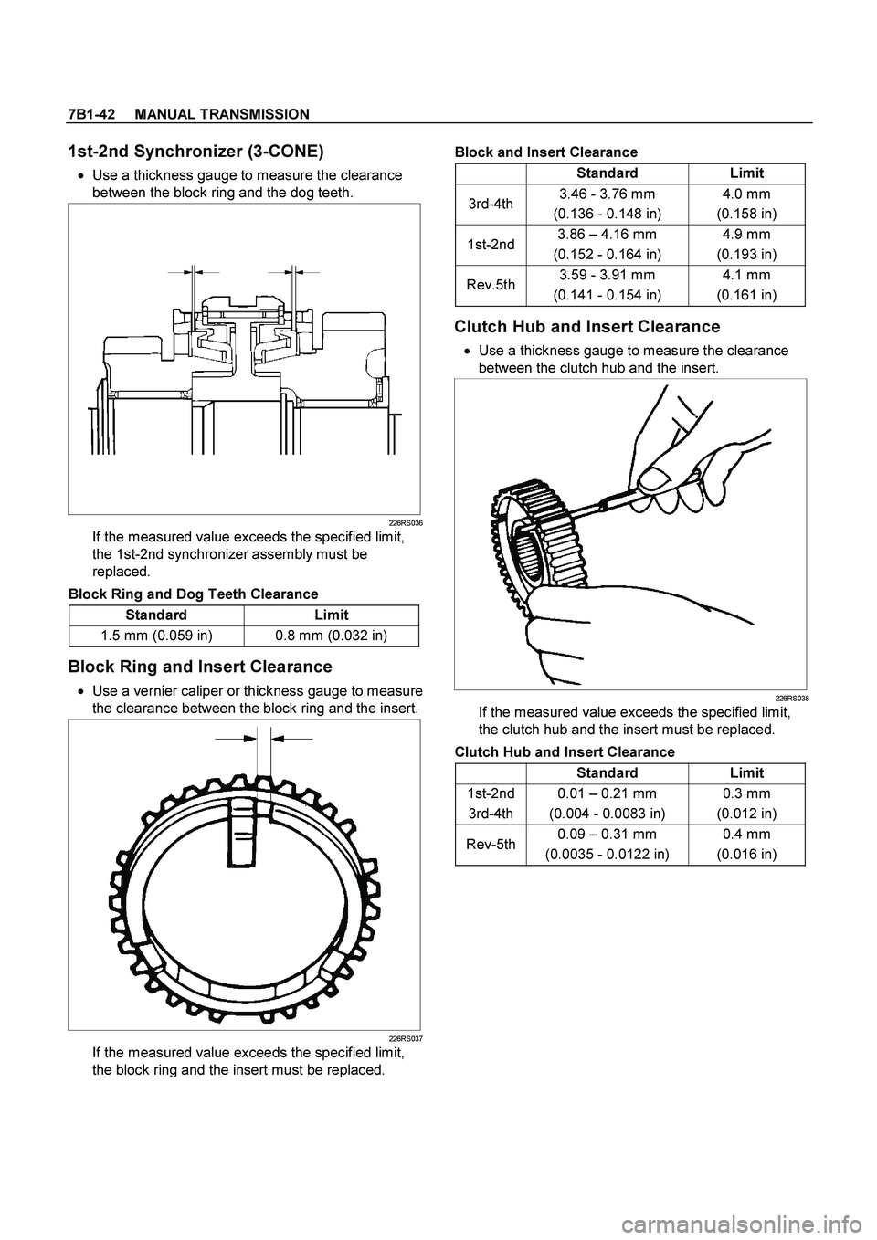
7B1-42 MANUAL TRANSMISSION
1st-2nd Synchronizer (3-CONE)
� Use a thickness gauge to measure the clearance
between the block ring and the dog teeth.
226RS036
If the measured value exceeds the specified limit,
the 1st-2nd synchronizer assembly must be
replaced.
Block Ring and Dog Teeth Clearance
Standard Limit
1.5 mm (0.059 in) 0.8 mm (0.032 in)
Block Ring and Insert Clearance
� Use a vernier caliper or thickness gauge to measure
the clearance between the block ring and the insert.
226RS037
If the measured value exceeds the specified limit,
the block ring and the insert must be replaced.
Block and Insert Clearance
Standard Limit
3rd-4th 3.46 - 3.76 mm
(0.136 - 0.148 in) 4.0 mm
(0.158 in)
1st-2nd3.86 – 4.16 mm
(0.152 - 0.164 in) 4.9 mm
(0.193 in)
Rev.5th3.59 - 3.91 mm
(0.141 - 0.154 in) 4.1 mm
(0.161 in)
Clutch Hub and Insert Clearance
�
Use a thickness gauge to measure the clearance
between the clutch hub and the insert.
226RS038
If the measured value exceeds the specified limit,
the clutch hub and the insert must be replaced.
Clutch Hub and Insert Clearance
Standard Limit
1st-2nd
3rd-4th 0.01 – 0.21 mm
(0.004 - 0.0083 in) 0.3 mm
(0.012 in)
Rev-5th0.09 – 0.31 mm
(0.0035 - 0.0122 in) 0.4 mm
(0.016 in)
Page 3210 of 4264
7B1-46 MANUAL TRANSMISSION
266RS049
7. Install the synchronizer assembly (20) to the
mainshaft (26).
The clutch hub face with the heavy boss must be
facing the 2nd gear side.
226RS048
8. Install clutch hub snap ring(19) by performing the
following steps:
� Select the snap ring which will provide the
minimum clearance between the 1st-2nd clutch
hub and the snap ring.
226RS050
�
There are three snap ring sizes available.
� The snap rings are color coded to indicate their
thickness as shown in the figure.
226RS021
Clutch Hub and Snap Ring Clearance
Standard: 0 - 0.1 mm (0 - 0.004 in)
Snap Ring Availability
Thickness Color Coding
1.80 mm (0.071 in) White
1.85 mm (0.073 in) Yellow
1.90 mm (0.075 in) Blue
�
Use a pair of snap ring pliers to install the snap
ring (19) to the mainshaft (26).
The snap ring must be fully inserted into the
mainshaft snap ring groove.