2004 ISUZU TF SERIES turn signal
[x] Cancel search: turn signalPage 107 of 4264
RESTRAINT CONTROL 9A1-37
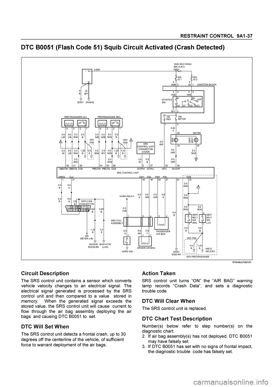
DTC B0051 (Flash Code 51) Squib Circuit Activated (Crash Detected)
RTW49JLF000101
Circuit Description
The SRS control unit contains a sensor which converts
vehicle velocity changes to an electrical signal. The
electrical signal generated is processed by the SRS
control unit and then compared to a value stored in
memory. When the generated signal exceeds the
stored value, the SRS control unit will cause current to
flow through the air bag assembly deploying the ai
r
bags and causing DTC B0051 to set.
DTC Will Set When
The SRS control unit detects a frontal crash, up to 30
degrees off the centerline of the vehicle, of sufficient
force to warrant deployment of the air bags.
Action Taken
SRS control unit turns “ON” the “AIR BAG” warning
lamp records “Crash Data”, and sets a diagnostic
trouble code.
DTC Will Clear When
The SRS control unit is replaced.
DTC Chart Test Description
Number(s) below refer to step number(s) on the
diagnostic chart:
2.
If air bag assembly(s) has not deployed, DTC B0051
may have falsely set.
3.
If DTC B0051 has set with no signs of frontal impact,
the diagnostic trouble code has falsely set.
Page 109 of 4264
RESTRAINT CONTROL 9A1-39
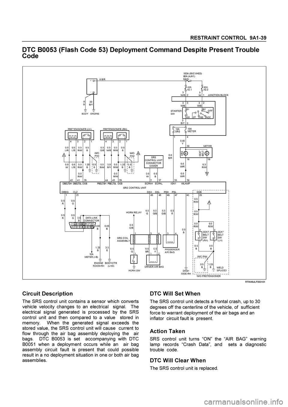
DTC B0053 (Flash Code 53) Deployment Command Despite Present Trouble
Code
RTW49JLF000101
Circuit Description
The SRS control unit contains a sensor which converts
vehicle velocity changes to an electrical signal. The
electrical signal generated is processed by the SRS
control unit and then compared to a value stored in
memory. When the generated signal exceeds the
stored value, the SRS control unit will cause current to
flow through the air bag assembly deploying the ai
r
bags. DTC B0053 is set accompanying with DTC
B0051 when a deployment occurs while an air bag
assembly circuit fault is present that could possible
result in a no deployment situation in one or both air bag
assemblies.
DTC Will Set When
The SRS control unit detects a frontal crash, up to 30
degrees off the centerline of the vehicle, of sufficient
force to warrant deployment of the air bags and an
inflator circuit fault is present.
Action Taken
SRS control unit turns “ON” the “AIR BAG” warning
lamp records “Crash Data”, and sets a diagnostic
trouble code.
DTC Will Clear When
The SRS control unit is replaced.
Page 131 of 4264

RESTRAINT CONTROL 9A1-61
DTC B1000 (Flash Code 72) SDM Internal Fault (SDM=SRS control unit)
RTW49JLF000101
Circuit Description
DTC B1000 is an indication of a potential internal SRS
control unit malfunction and will set if any of the
following conditions are detected:
1) Microprocessor energy reverse time failure.
2) EEPROM read / write failure.
3) ROM check sum.
4) Calibration check sum fault.
5) Inflators reserve voltage low.
6) Inflators electronic sensor active signal not detected
during commanded deployment.
7) QSDD (High-side/Low-side) FET failure.
8) Frontal accelerometer failure.
9) Phase lock loop lost lock.
10) QSDD communication fault.
DTC Will Set When
Any of the above indicated malfunctions are detected by
the SRS control unit. The malfunctions described
above are tested mainly during “Continuous Monitoring”
and some ones run each ignition cycle.
Action Taken
SRS control unit turns “ON” the “AIR BAG” warning
lamp and sets a diagnostic trouble code.
DTC Will Clear When
SRS control unit is replaced.
Page 335 of 4264
BRAKE CONTROL SYSTEM 5A-19
System Components
Electronic Hydraulic Control Unit (EHCU), four Wheel
Speed Sensors, two Warning Lamps, and G-sensor.
Electronic Hydraulic Control Unit (EHCU)
The EHCU consists of ABS control circuits, fault
detector, and a fail-safe. It drives the EHCU according
to the signal from each sensor, cancelling ABS to return
to normal braking when a malfunction has occurred in
the ABS.
The EHCU has a self-diagnosing function which can
indicate faulty circuits during diagnosis.
The EHCU is mounted on the engine compartment rear
left side. It consists of a motor, solenoid valves fail safe
relay.
Solenoid Valves: Reduces or holds the caliper fluid
pressure for each front brake or both rear brakes
according to the signal sent from the EHCU.
Buffer chamber: Temporarily holds the brake fluid that
returns from the front and rear brake so that pressure
of front brake can be reduced smoothly.
Motor: Drives the pump according to the signal from
EHCU.
Fail safe Relay: When failure occurs in ABS.
The power supply to solenoid Valve is cut.
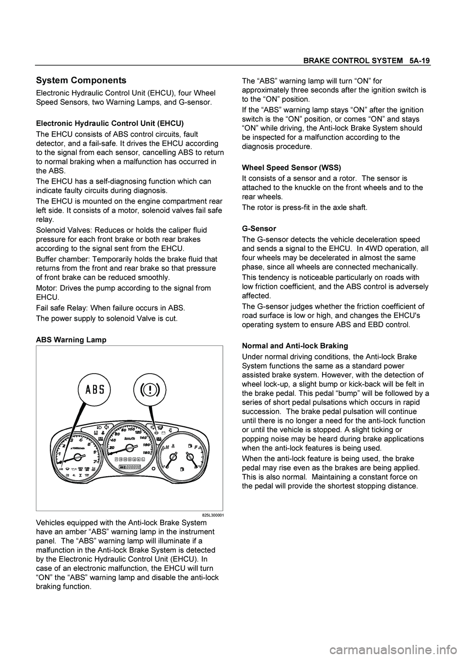
ABS Warning Lamp
825L300001
Vehicles equipped with the Anti-lock Brake System
have an amber “ABS” warning lamp in the instrument
panel. The “ABS” warning lamp will illuminate if a
malfunction in the Anti-lock Brake System is detected
by the Electronic Hydraulic Control Unit (EHCU). In
case of an electronic malfunction, the EHCU will turn
“ON” the “ABS” warning lamp and disable the anti-lock
braking function.
The “ABS” warning lamp will turn “ON” for
approximately three seconds after the ignition switch is
to the “ON” position.
If the “ABS” warning lamp stays “ON” after the ignition
switch is the “ON” position, or comes “ON” and stays
“ON” while driving, the Anti-lock Brake System should
be inspected for a malfunction according to the
diagnosis procedure.
Wheel Speed Sensor (WSS)
It consists of a sensor and a rotor. The sensor is
attached to the knuckle on the front wheels and to the
rear wheels.
The rotor is press-fit in the axle shaft.
G-Sensor
The G-sensor detects the vehicle deceleration speed
and sends a signal to the EHCU. In 4WD operation, all
four wheels may be decelerated in almost the same
phase, since all wheels are connected mechanically.
This tendency is noticeable particularly on roads with
low friction coefficient, and the ABS control is adversely
affected.
The G-sensor judges whether the friction coefficient of
road surface is low or high, and changes the EHCU's
operating system to ensure ABS and EBD control.
Normal and Anti-lock Braking
Under normal driving conditions, the Anti-lock Brake
System functions the same as a standard power
assisted brake system. However, with the detection of
wheel lock-up, a slight bump or kick-back will be felt in
the brake pedal. This pedal “bump” will be followed by a
series of short pedal pulsations which occurs in rapid
succession. The brake pedal pulsation will continue
until there is no longer a need for the anti-lock function
or until the vehicle is stopped. A slight ticking or
popping noise may be heard during brake applications
when the anti-lock features is being used.
When the anti-lock feature is being used, the brake
pedal may rise even as the brakes are being applied.
This is also normal. Maintaining a constant force on
the pedal will provide the shortest stopping distance.
Page 660 of 4264
8A-2 ELECTRICAL-BODY AND CHASSIS
PAGE
Fuse and Slow Blow Fuse Location (Relay and Fuse Box) .................................... 8A- 31
Fuse Location ............................................................................................................. 8A- 33
Diode Location ........................................................................................................... 8A- 34
Fuse Block Circuit ...................................................................................................... 8A- 35
Fuse Block Circuit (C24SE) ....................................................................................... 8A- 35
Fuse Block Circuit (6VE1) ......................................................................................... 8A- 37
Fuse Block Circuit (4JA1-TC/4JH1-TC) - RHD ......................................................... 8A- 39
Fuse Block Circuit (4JA1-TC/4JH1-TC) – LHD ......................................................... 8A- 41
Fuse Block Circuit (4JH1-L) ...................................................................................... 8A- 43
Grounding Point ............................................................................................................. 8A- 45
Ground Point .............................................................................................................. 8A- 45
Ground Point Location .............................................................................................. 8A- 61
Main Cable harness Routing .......................................................................................... 8A- 63
C24SE / 6VE1 / 4JA1-L / 4JH1-TC .............................................................................. 8A- 63
Instrument Harness .................................................................................................... 8A- 71
System Repair .................................................................................................................8A- 73
Start and Charging ..................................................................................................... 8A- 73
Engine Control Module (ECM) ................................................................................... 8A- 89
Exhaust Gas Recalculation (EGR): 4JA1-L Only ...................................................... 8A- 109
Lighting ....................................................................................................................... 8A- 114
Front Fog Light ........................................................................................................... 8A- 136
Rear Fog Light ............................................................................................................ 8A- 144
Head Light Leveling ................................................................................................... 8A- 149
Illumination ................................................................................................................. 8A- 154
Hazard Warning Flasher, Turn Signal Light, Back Up Light,
Horn and Stop Light ................................................................................................. 8A- 161
Dome Light, Spot Light and Warning Buzzer .......................................................... 8A- 181
Windshield Wiper and Washer .................................................................................. 8A- 196
Transmission Control Module (TCM) ....................................................................... 8A- 214
Meter, Warning Light and Indicator Light ................................................................ 8A- 223
Heater and Air Conditioning ...................................................................................... 8A- 281
Power Door Lock ....................................................................................................... 8A- 293
Page 682 of 4264
8A-24 ELECTRICAL-BODY AND CHASSIS
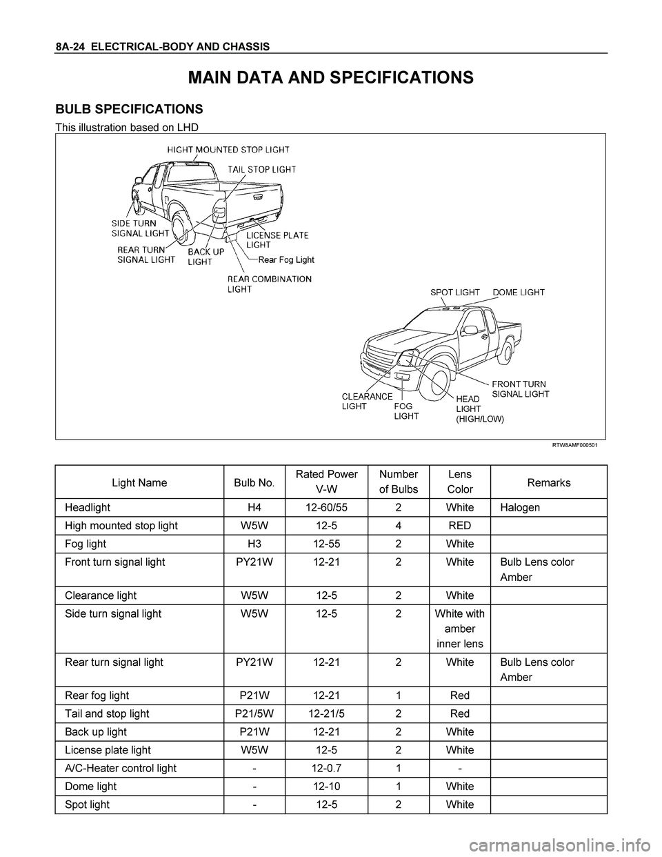
MAIN DATA AND SPECIFICATIONS
BULB SPECIFICATIONS
This illustration based on LHD
RTW8AMF000501
Light Name Bulb No. Rated Power
V-W Number
of Bulbs Lens
Color Remarks
Headlight H4 12-60/55 2 White Halogen
High mounted stop light W5W 12-5 4 RED
Fog light H3 12-55 2 White
Front turn signal light PY21W 12-21 2 White Bulb Lens color
Amber
Clearance light W5W 12-5 2 White
Side turn signal light W5W 12-5 2 White with
amber
inner lens
Rear turn signal light PY21W 12-21 2 White Bulb Lens color
Amber
Rear fog light P21W 12-21 1 Red
Tail and stop light P21/5W 12-21/5 2 Red
Back up light P21W 12-21 2 White
License plate light W5W 12-5 2 White
A/C-Heater control light - 12-0.7 1 -
Dome light - 12-10 1 White
Spot light - 12-5 2 White
Page 683 of 4264
ELECTRICAL-BODY AND CHASSIS 8A-25
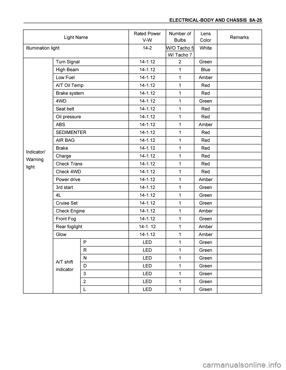
Light Name Rated Power
V-W Number of
Bulbs Lens
Color Remarks
W/O Tacho 5Illumination light 14-2
W/ Tacho 7White
Turn Signal 14-1.12 2 Green
High Beam 14-1.12 1 Blue
Low Fuel 14-1.12 1 Amber
A/T Oil Temp 14-1.12 1 Red
Brake system 14-1.12 1 Red
4WD 14-1.12 1 Green
Seat belt 14-1.12 1 Red
Oil pressure 14-1.12 1 Red
ABS 14-1.12 1 Amber
SEDIMENTER 14-1.12 1 Red
AIR BAG 14-1.12 1 Red
Brake 14-1.12 1 Red
Charge 14-1.12 1 Red
Check Trans 14-1.12 1 Red
Check 4WD 14-1.12 1 Red
Power drive 14-1.12 1 Amber
3rd start 14-1.12 1 Green
4L 14-1.12 1 Green
Cruise Set 14-1.12 1 Green
Check Engine 14-1.12 1 Amber
Front Fog 14-1.12 1 Green
Rear foglight 14-1. 12 1 Amber
Glow 14-1.12 1 Amber
P LED 1 Green
R LED 1 Green
N LED 1 Green
D LED 1 Green
3 LED 1 Green
2 LED 1 Green
Indicator/
Warning
light
A/T shift
indicator
L LED 1 Green
Page 819 of 4264

ELECTRICAL-BODY AND CHASSIS 8A-161
HAZARD WARNING FLASHER, TURN SIGNAL LIGHT, BACK UP
LIGHT, HORN AND STOP LIGHT
PARTS LOCATION (RHD)
RTW48AXF016601 & RTW48AXF016701