Page 4057 of 4264
DIAGNOSIS (JR405E) 7A2-65
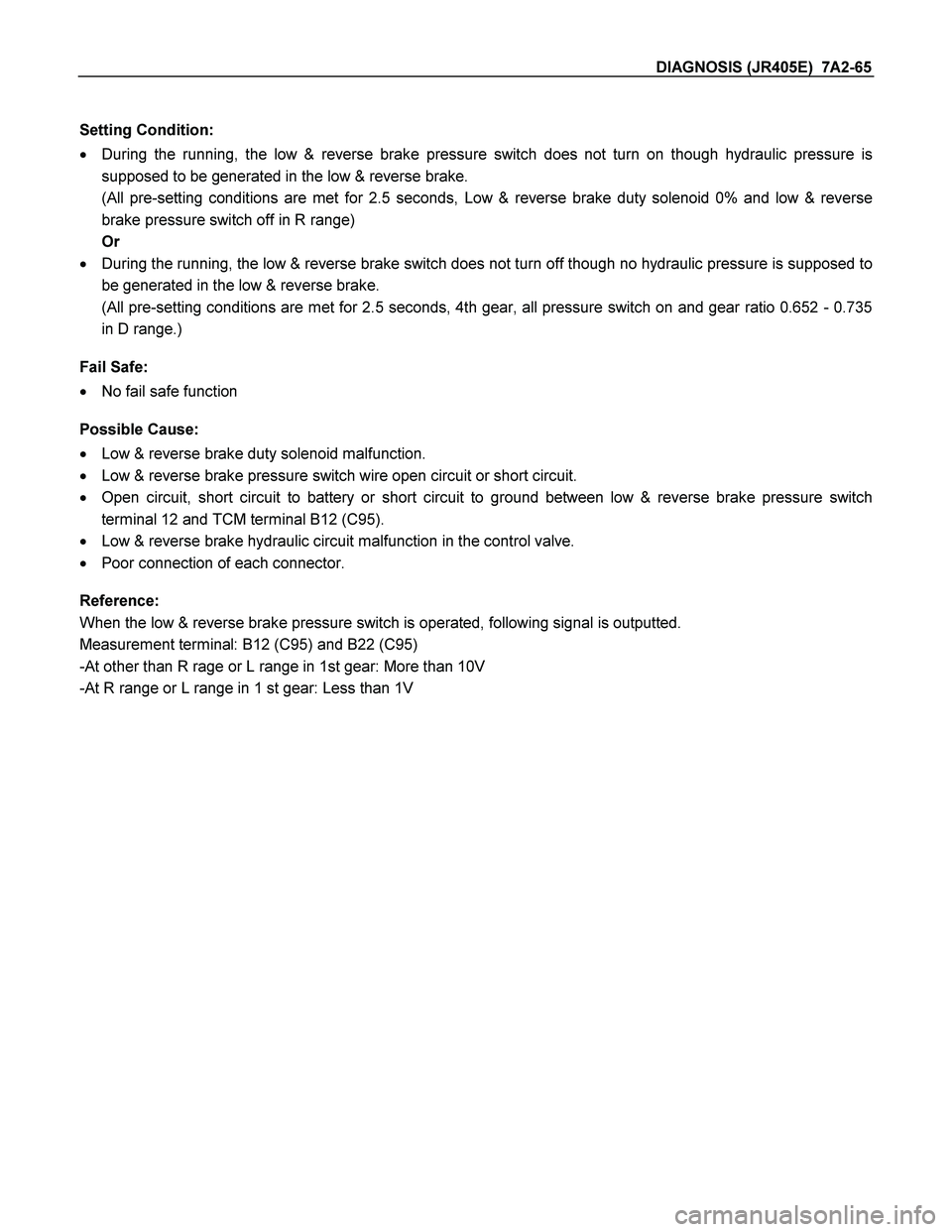
Setting Condition:
� During the running, the low & reverse brake pressure switch does not turn on though hydraulic pressure is
supposed to be generated in the low & reverse brake.
(All pre-setting conditions are met for 2.5 seconds, Low & reverse brake duty solenoid 0% and low & reverse
brake pressure switch off in R range)
Or
� During the running, the low & reverse brake switch does not turn off though no hydraulic pressure is supposed to
be generated in the low & reverse brake.
(All pre-setting conditions are met for 2.5 seconds, 4th gear, all pressure switch on and gear ratio 0.652 - 0.735
in D range.)
Fail Safe:
� No fail safe function
Possible Cause:
� Low & reverse brake duty solenoid malfunction.
� Low & reverse brake pressure switch wire open circuit or short circuit.
� Open circuit, short circuit to battery or short circuit to ground between low & reverse brake pressure switch
terminal 12 and TCM terminal B12 (C95).
� Low & reverse brake hydraulic circuit malfunction in the control valve.
� Poor connection of each connector.
Reference:
When the low & reverse brake pressure switch is operated, following signal is outputted.
Measurement terminal: B12 (C95) and B22 (C95)
-At other than R rage or L range in 1st gear: More than 10V
-At R range or L range in 1 st gear: Less than 1V
Page 4061 of 4264
DIAGNOSIS (JR405E) 7A2-69
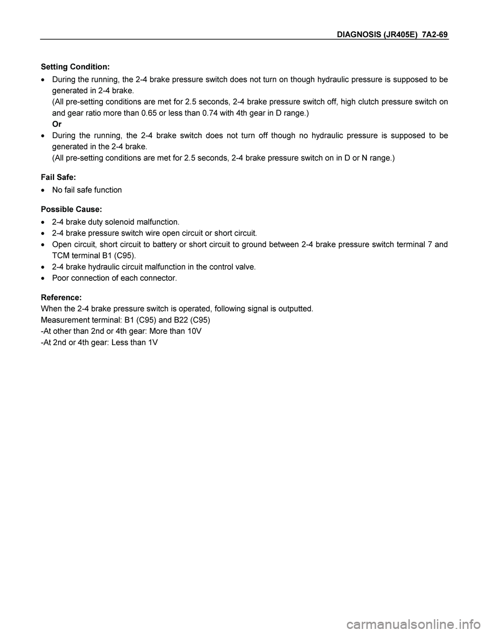
Setting Condition:
� During the running, the 2-4 brake pressure switch does not turn on though hydraulic pressure is supposed to be
generated in 2-4 brake.
(All pre-setting conditions are met for 2.5 seconds, 2-4 brake pressure switch off, high clutch pressure switch on
and gear ratio more than 0.65 or less than 0.74 with 4th gear in D range.)
Or
� During the running, the 2-4 brake switch does not turn off though no hydraulic pressure is supposed to be
generated in the 2-4 brake.
(All pre-setting conditions are met for 2.5 seconds, 2-4 brake pressure switch on in D or N range.)
Fail Safe:
� No fail safe function
Possible Cause:
� 2-4 brake duty solenoid malfunction.
� 2-4 brake pressure switch wire open circuit or short circuit.
� Open circuit, short circuit to battery or short circuit to ground between 2-4 brake pressure switch terminal 7 and
TCM terminal B1 (C95).
� 2-4 brake hydraulic circuit malfunction in the control valve.
� Poor connection of each connector.
Reference:
When the 2-4 brake pressure switch is operated, following signal is outputted.
Measurement terminal: B1 (C95) and B22 (C95)
-At other than 2nd or 4th gear: More than 10V
-At 2nd or 4th gear: Less than 1V
Page 4065 of 4264
DIAGNOSIS (JR405E) 7A2-73
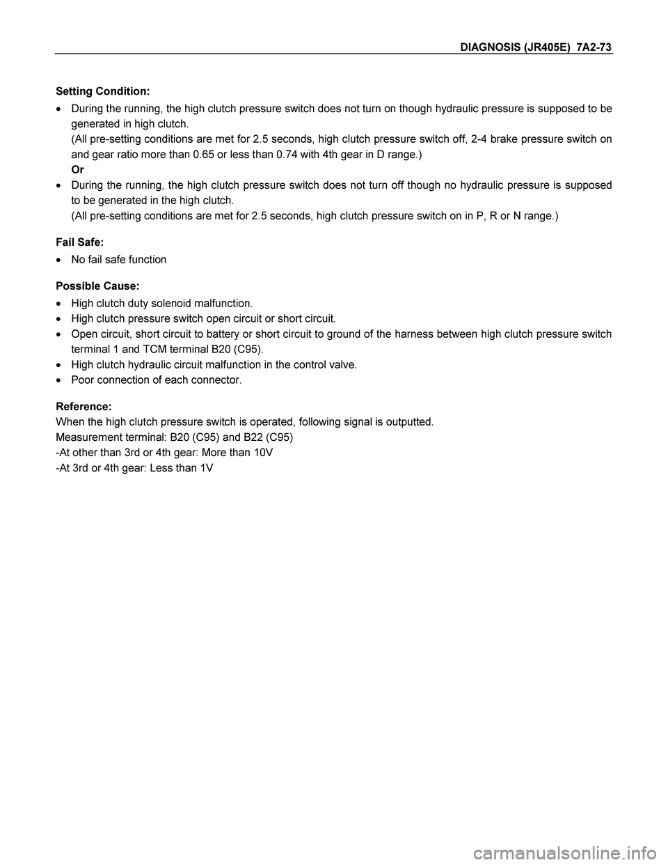
Setting Condition:
� During the running, the high clutch pressure switch does not turn on though hydraulic pressure is supposed to be
generated in high clutch.
(All pre-setting conditions are met for 2.5 seconds, high clutch pressure switch off, 2-4 brake pressure switch on
and gear ratio more than 0.65 or less than 0.74 with 4th gear in D range.)
Or
� During the running, the high clutch pressure switch does not turn off though no hydraulic pressure is supposed
to be generated in the high clutch.
(All pre-setting conditions are met for 2.5 seconds, high clutch pressure switch on in P, R or N range.)
Fail Safe:
� No fail safe function
Possible Cause:
� High clutch duty solenoid malfunction.
� High clutch pressure switch open circuit or short circuit.
� Open circuit, short circuit to battery or short circuit to ground of the harness between high clutch pressure switch
terminal 1 and TCM terminal B20 (C95).
� High clutch hydraulic circuit malfunction in the control valve.
� Poor connection of each connector.
Reference:
When the high clutch pressure switch is operated, following signal is outputted.
Measurement terminal: B20 (C95) and B22 (C95)
-At other than 3rd or 4th gear: More than 10V
-At 3rd or 4th gear: Less than 1V
Page 4097 of 4264
DIAGNOSIS (JR405E) 7A2-105
Step Action Yes No
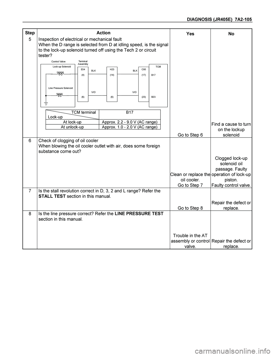
5 Inspection of electrical or mechanical fault
When the D range is selected from D at idling speed, is the signal
to the lock-up solenoid turned off using the Tech 2 or circuit
tester?
Control Valve
TCM
B17
B23 BLK Lock-up Solenoid
Te rm i n a l
Assembly
VIO Line Pressure Solenoid
E54
(4)
(6)H23
(14)
(6)C95
(17)
(23) BLK
VIO
TCM terminal
Lock-upB17
At lock-up Approx. 2.2 - 9.0 V (AC range)
At unlock-up Approx. 1.0 - 2.0 V (AC range)
Go to Step 6
Find a cause to turn
on the lockup
solenoid
6 Check of clogging of oil cooler
When blowing the oil cooler outlet with air, does some foreign
substance come out?
Clean or replace the
oil cooler.
Go to Step 7
Clogged lock-up
solenoid oil
passage. Faulty
operation of lock-up
piston.
Faulty control valve.
7 Is the stall revolution correct in D, 3, 2 and L range? Refer the
STALL TEST section in this manual.
Go to Step 8
Repair the defect or
replace.
8 Is the line pressure correct? Refer the LINE PRESSURE TEST
section in this manual.
Trouble in the AT
assembly or control
valve.
Repair the defect or
replace.
Page 4112 of 4264
7A2-120 DIAGNOSIS (JR405E)
No. D2: Gear is Shifted Frequently
Description:
� Gear is shifted down immediately though the accelerator pedal is stepped on a little in D, 3, 2, or L range.
Diagnosis Hints:
� Basically, the same cause as "No. D1: Faulty gear shifting" is considered. However, as possible cause, fault
input signal of throttle position sensor or speed sensor, fault input signal of inhibitor switch, or fault of TCM
power source, earth, ground return wire are considered first.
� Then, slip of the clutch, fault of the control valve are considered.
No. D3: Gear Shift Point is Low or High at All Point
No. D4: Gear Shift Point is Low or High at Limited Point
Description:
� Gear shift point is deviated from the shift diagram.
� Gear is not shifted up properly though the vehicle is accelerated.
� Gear is not shifted immediately and enough acceleration cannot be obtained though the accelerator pedal is
stepped on.
Diagnosis Hints:
� If the cause is not faulty gear shift, throttle position sensor disordered or fault input of speed sensor is
considered. Output signal of the throttle position sensor is changed to linear one.
(Refer the paragraph about the faulty throttle position sensor of "No. D1: Faulty gear shifting".)
No. D5: No Kick-down
Description:
� The engine speeds up but vehicle speed does not increase when the accelerator pedal is stepped on at the
starting.
Diagnosis Hints:
� When the gear shift is normal only without kick-down, possibility of fault of the throttle position sensor. Check
that the throttle voltage increases linearly in proportion to the throttle opening.
(Refer the paragraph about the faulty throttle position sensor of "No. D1: Faulty gear shifting".)