Page 146 of 4264

4A-10 PROPELLER SHAFT
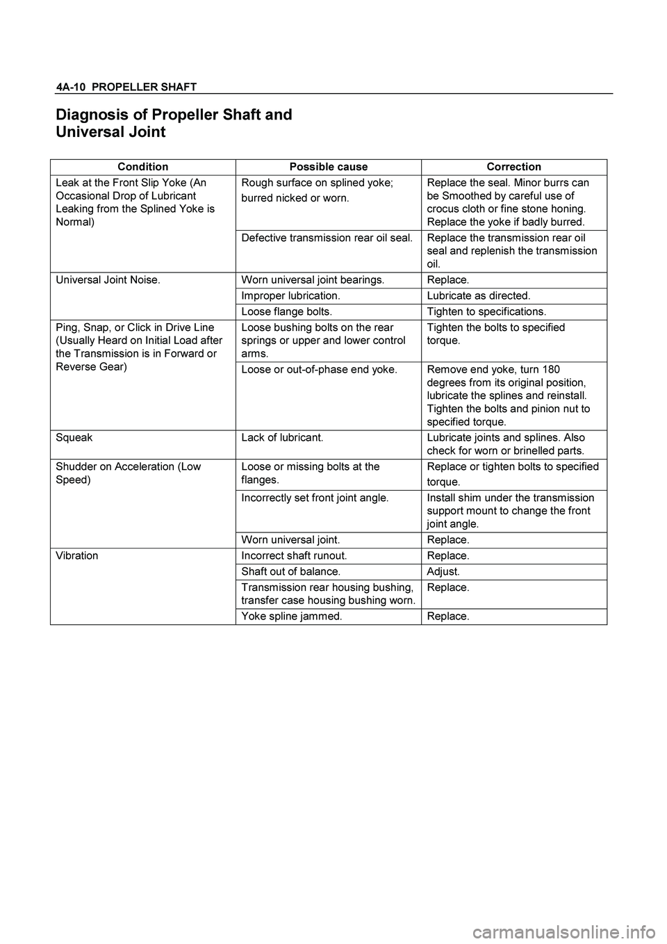
Diagnosis of Propeller Shaft and
Universal Joint
Condition Possible cause Correction
Rough surface on splined yoke;
burred nicked or worn. Replace the seal. Minor burrs can
be Smoothed by careful use of
crocus cloth or fine stone honing.
Replace the yoke if badly burred. Leak at the Front Slip Yoke (An
Occasional Drop of Lubricant
Leaking from the Splined Yoke is
Normal)
Defective transmission rear oil seal. Replace the transmission rear oil
seal and replenish the transmission
oil.
Worn universal joint bearings. Replace.
Improper lubrication. Lubricate as directed.
Universal Joint Noise.
Loose flange bolts. Tighten to specifications.
Loose bushing bolts on the rear
springs or upper and lower control
arms. Tighten the bolts to specified
torque. Ping, Snap, or Click in Drive Line
(Usually Heard on Initial Load after
the Transmission is in Forward or
Reverse Gear)
Loose or out-of-phase end yoke. Remove end yoke, turn 180
degrees from its original position,
lubricate the splines and reinstall.
Tighten the bolts and pinion nut to
specified torque.
Squeak Lack of lubricant. Lubricate joints and splines. Also
check for worn or brinelled parts.
Loose or missing bolts at the
flanges. Replace or tighten bolts to specified
torque.
Incorrectly set front joint angle. Install shim under the transmission
support mount to change the front
joint angle.
Shudder on Acceleration (Low
Speed)
Worn universal joint. Replace.
Incorrect shaft runout. Replace.
Shaft out of balance. Adjust.
Transmission rear housing bushing,
transfer case housing bushing worn.Replace.
Vibration
Yoke spline jammed. Replace.
Page 147 of 4264

PROPELLER SHAFT 4A-11
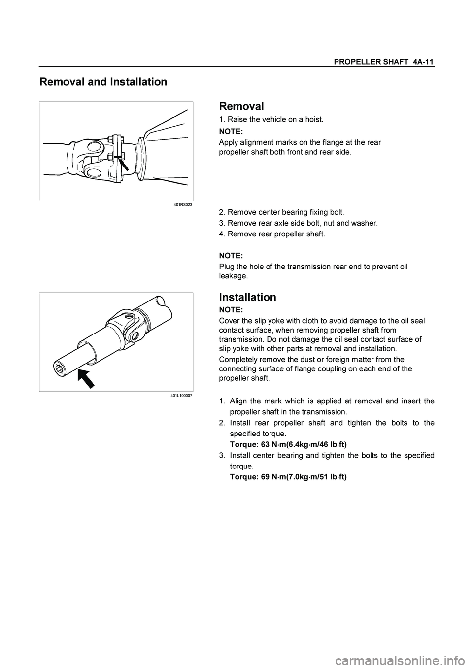
Removal and Installation
401RS023
Removal
1. Raise the vehicle on a hoist.
NOTE:
Apply alignment marks on the flange at the rear
propeller shaft both front and rear side.
2. Remove center bearing fixing bolt.
3. Remove rear axle side bolt, nut and washer.
4. Remove rear propeller shaft.
NOTE:
Plug the hole of the transmission rear end to prevent oil
leakage.
401L100007
Installation
NOTE:
Cover the slip yoke with cloth to avoid damage to the oil seal
contact surface, when removing propeller shaft from
transmission. Do not damage the oil seal contact surface of
slip yoke with other parts at removal and installation.
Completely remove the dust or foreign matter from the
connecting surface of flange coupling on each end of the
propeller shaft.
1.
Align the mark which is applied at removal and insert the
propeller shaft in the transmission.
2. Install rear propeller shaft and tighten the bolts to the
specified torque.
Torque: 63 N�
�� �m(6.4kg�
�� �m/46 lb�
�� �ft)
3. Install center bearing and tighten the bolts to the specified
torque.
Torque: 69 N
�
�� �m(7.0kg
�
�� �m/51 lb
�
�� �ft)
Page 223 of 4264
FRONT WHEEL DRIVE 4C1-3
MAIN DATA AND SPECIFICATIONS
FRONT AXLE AND DIFFERENTIAL
Ring gear size mm (in) 194 (7.6)
Axle tube
Type It consists of the duce, a cast iron housing and the Axle tube.
Gear type Hypoid
Gear ratio (to 1) 4.100, 4.300, 4.555, 4.777, 5125
Differential type Two pinion
Specified gear oil (APL grade) GL-5
Oil capacity liter 1.4
(US/UK gal.) (0.4/0.33)
Axle shaft type Constant velocity joint (Birfield joint type and double offset joint).
FRONT PROPELLER SHAFT mm(in)
4�
4 Model
Engine Model 4JA1-T(L) 4JA1-TC 4JH1-TC C24SE 6VE1
Transmission Type 5M/T (MUA) 5M/T
(MUA) 4A/T 5M/T
(MUA) 5M/T
(MUA) 4A/T
Front Axle 194 mm �
�
�
�
�
Outside Diameter mm 40 40 40 40 40 40
(in) (1.57) (1.57) (1.57) (1.57) (1.57) (1.57)
Inside Diameter mm 32 32 32 32 32 32
(in) (1.26) (1.26) (1.26) (1.26) (1.26) (1.26)
Length (L) mm 607 607 676 586 586 607
(in) (23.90) (23.90) (26.61) (23.07) (23.07) (23.90)
Fix Bolt Size T/F M10 M10 M10 M10 M10 M10
Axle M10 M10 M10 M10 M10 M10
Page 632 of 4264

7C-30 CLUTCH
Shift Fork
1. Visually inspect the surfaces of the shift fork making contact
with the release bearing for excessive wear and damage.
2. Remove any minor stepping or abrasion from the release
bearing with an oil stone.
Replace any exhibiting excessive wear or damage.
3. Apply multi-purpose type grease (NLGI No.2 or No.3) to
area.
DRIVEN PLATE ASSEMBLY
1. Visually inspect the torsion spring
1 for looseness,
breakage, and weakening.
If any of these conditions are discovered, the driven plate
assembly must be replaced.
2. Visually inspect the facing surfaces
2 for cracking and
excessive scorching.
Visually inspect the facing surfaces for the presence of oil
or grease.
If any of these conditions are discovered, the facing mus
t
be cleaned or replaced.
3. Check that the driven plate moves smoothly on the
transmission top gear shaft spline.
Minor ridges on the top gear shaft spline may be removed
with an oil stone.
Driven Plate Warpage
1. Insert the clutch pilot aligner into the driven plate splined
hub.
The clutch pilot aligner must be held perfectly horizontal.
Clutch Pilot Aligner : 5-8525-3001-0
2. Set a dial indicator to the driven plate outside
circumference.
3. Slowly turn the driven plate.
Read the dial indicator as you turn the driven plate.
If the measured value exceeds the specified limit, the driven
plate assembly and/or the facing must be replaced.
Driven Plate Warpage mm(in)
Standard Limit
0.7 (0.028) 1.0 (0.039)
Page 645 of 4264
CLUTCH 7C-43
1. CLUTCH SLIPPAGE
Checkpoint
Trouble Cause
Countermeasure
Adjust the push rod play
No push rod play in the master
cylinder
NG
Clutch pedal free play
Clean the related parts and/or
replace the facing
Replace the transmission front
cover oil seal
Clean the related parts and/or
replace the facing
Repair or replace the
transmission front cover
Defective transmission front
cover oil seal
Continued on the next page
Grease or oil adhering to the
facing
Too much grease
Transmission front cover
unevenly worn
Clean and grease the release
bearing
Release bearing
Insufficient grease on the front
cover contact surfaces
NG NG NG NG OK
OK
OK
Page 649 of 4264
CLUTCH 7C-47
3. CLUTCH SHUDDER
Checkpoint
Trouble Cause
Countermeasure
Grease or oil adhering to the
facing
Clean the related parts and/or
replace the facing
Replace the transmission front
cover oil seal
Replace the pressure plate
assembly
Defective transmission front
cover oil seal
Pressure plate unevenly wornPressure plate
Clean the related parts and/or
replace the facing
Tighten the connections
Repair or replace the
applicable parts
Too much grease
Poorly connected components
causing looseness and
abrasion
OK
NG NG NG NG
OK
Power train
Clean and grease the spline
contact surface
Insufficient grease on the
spline contact surface of the
splined hub
Driven plate
Clean or repair the top gear
shaft spline
Replace the top gear shaft
Clean the related parts and/or
replace the facing
Replace the crankshaft rear oil
seal
Corrosion or step wear on the
top gear shaft spline
Defective crankshaft rear oil
seal
OKNG NG NG
OK
Continued on the next page
Page 1089 of 4264
ELECTRICAL-BODY AND CHASSIS 8A-431
No. Connector face No. Connector face
E-71
NOT USED E-80
(6VE1)
Cylinder revolution
E-72
(C24SE)
(6VE1)
Engine earth-A E-81
(6VE1)
Speed sensor
E-73
(6VE1)
Engine earth-A E-82
(6VE1)
Transmission wire
E-74
(C24SE)
(6VE1)
Engine earth-B E-83
(6VE1)
Oil temperature sensor
E-75
(C24SE)
(6VE1)
Oil pressure switch E-84
(C24SE)
Knock sensor
E-76
(6VE1)
EGR valve E-85
(C24SE)
MAP sensor
E-77
(C24SE)
O2 sensor E-86
(4JA1-L)
SilverThermo switch; QOS
E-77
(6VE1)
O2 sensor RH-Front E-87
(4JA1-L)
WhiteSolenoid CSD
E-78
(6VE1)
O2 sensor LH-Front E-88
(4JA1-L)
SilverThermo switch; EGR
E-79
(6VE1)
Neutral start switch E-89
(4JA1-L)
White
Immobilizer engine control unit
Page 1181 of 4264

ENGINE MECHANICAL 6A – 41
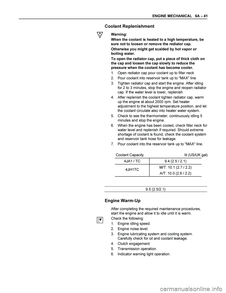
Coolant Replenishment
Warning:
When the coolant is heated to a high temperature, be
sure not to loosen or remove the rediator cap.
Otherwise you might get scalded by hot vapor or
boiling water.
To open the radiator cap, put a piece of thick cloth on
the cap and loosen the cap slowly to reduce the
pressure when the coolant has become cooler.
1. Open rediator cap pour coolant up to filler neck
2. Pour coolant into reservoir tank up to "MAX" line
3. Tighten radiator cap and start the engine. After idling
for 2 to 3 minutes, stop the engine and reopen radiator
cap. If the water level is lower, replenish.
4. After replenish the coolant tighten radiator cap, warm
up the engine at about 2000 rpm. Set heater
adjustment to the highest temperature position, and let
the coolant circulate also into heater water system.
5. Check to see the thermometer, continuously idling 5
minutes and stop the engine.
6. When the engine has been cooled, check filler neck for
water level and replenish if required. Should extreme
shortage of coolant is found, check the coolant system
and reservoir tank hose for leakage.
7. Pour coolant into the reservoir tank up to "MAX" line.
Coolant Capacity lit (US/UK gal)
4JA1 / TC 9.4 (2.5 / 2.1)
4JH1TC M/T: 10.1 (2.7 / 2.2)
A/T: 10.0 (2.6 / 2.2)
9.5 (2.5/2.1)
Engine Warm-Up
After completing the required maintenance procedures,
start the engine and allow it to idle until it is warm.
Check the following:
1. Engine idling speed.
2. Engine noise level.
3. Engine lubricating system and cooling system.
Carefully check for oil and coolant leakage.
4. Clutch engagement.
5. Transmission operation.
6. Indicator warning light operation.