Page 165 of 4264

REAR AXLE 4B-1
SECTION 4B
REAR AXLE
TABLE OF CONTENTS
PAGE
Main Data and Specifications ........................................................................................... 4B- 3
Torque Specifications....................................................................................................................4B- 4
Recommended Liquid Gasket .......................................................................................... 4B- 6
Recommended Thread Locking Agents .......................................................................... 4B- 6
Rear Axle Assembly .......................................................................................................... 4B- 7
General Description ...................................................................................................... 4B- 7
Servicing............................................................................................................................. 4B- 8
Rear Axle ............................................................................................................................ 4B- 9
Disassembly .................................................................................................................. 4B- 10
Inspection and Repair................................................................................................... 4B- 13
Reassembly ................................................................................................................... 4B- 14
Differential Assembly.....................................................................................................................4B- 19
Disassembly .................................................................................................................. 4B- 20
Reassembly ................................................................................................................... 4B- 22
Differential Cage Assembly..........................................................................................................4B- 32
Disassembly .................................................................................................................. 4B- 33
Inspection and Repair...............................................................................................................4B- 33
Reassembly.................................................................................................................................4B- 35
Limited Slip Differential (LSD) .......................................................................................... 4B- 36
Disassembly................................................................................................................................4B- 37
Inspection and Repair................................................................................................... 4B- 38
Reassembly ................................................................................................................... 4B- 40
Troubleshooting ............................................................................................................ 4B- 43
Special Service Tool..................................................................................................................4B- 54
Page 167 of 4264
REAR AXLE 4B-3
MAIN DATA AND SPECIFICATIONS
REAR AXLE
Ring gear size mm(in)220 (8.66)
Rear axle type Banjo, semi-floating
Rear axle capacity N (kg/lb)16475 (1680/3700)
Rear axle case 16965 (1730/3815) (EC)
Axle tube section
Outside diameter mm(in)80 (3.15)
Thickness mm(in)4.5 (0.118)
Final drive type Single speed
Final gear type Hypoid
Drive pinion bearing preload kg-cm(lb.in)
Starting torque (At drive pinion flange nut) 7-13 (6.1-11.3)
Preload adjusting method Collapsible
Final gear backlash mm(in)0.15-0.20 (0.006-0.008)
Differential carrier assembly
Weight (Dry) kg/lb29.0/63.9
Lubrication
Specified gear oil (APL grade) GL5 (STD), GL5LSD (LSD)
Oil capacity lit (US/UK gal)2.4 (0.63/0.53)
Page 169 of 4264
REAR AXLE 4B-5
Differential
N�m (kgf�m/lb�ft)
RTW34BLF000201
Page 171 of 4264

REAR AXLE 4B-7
REAR AXLE ASSEMBLY
General Description
A03R300001
The rear axle assembly is of the semi–floating type in
which the vehicle weight is carried on the axle
housing .
The center line of the pinion gear is below the center
line of the ring gear (hypoid drive).
All parts necessary to transmit power from the
propeller shaft to the rear wheels are enclosed in a
banjo type axle housing.
The 220 mm (8.6 in) ring gear rear axle uses a
conventional ring and pinion gear set to transmit the
driving force of the engine to the rear wheels. This
gear set transfers this driving force at a 90 degree
angle from the propeller shaft to the drive shafts.
The axle shafts are supported at the wheel end of the
shaft by a double tapered roller bearing.
The pinion gear is supported by two tapered roller
bearings. The pinion depth is set by a shim pack
located between the gear end of the pinion and the
roller bearing that is pressed onto the pinion. The
pinion bearing preload is set by crushing a collapsible
spacer between the bearings in the axle housing.
The ring gear is bolted onto the differential cage with
12 bolts.
The differential cage is supported in the axle housing
by two tapered roller bearings. The differential and ring
gear are located in relationship to the pinion by using
selective shims and spacers between the bearing and
the differential cage. To move the ring gear, shims are
deleted from one side and an equal amount are added
to the other side. These shims are also used to
preload the bearings which are pressed onto the
differential cage. Two bearing caps are used to hold
the differential into the rear axle housing.
The differential is used to allow the wheels to turn at
different rates of speed while the rear axle continues
to transmit the driving force. This prevents tire
scuffing when going around corners and prevents
premature wear on internal axle parts.
The rear axle is sealed with a pinion seal, a seal at
each axle shaft end, and by a liquid gasket between
the differential carrier and the axle housing
Page 173 of 4264
REAR AXLE 4B-9
REAR AXLE
1.
Refer to Section 3E "WHEEL and TIRE" for road
wheel Disassembly procedure.
2.
Refer to Section 5 "BRAKE" for rear brake
removal procedure.
RTW34BLF000401
Legend
1. Brake Drum
2. Bolt and Nut
3. Axle Shaft Assembly with Brake
4.
Shim
5. Snap Ring
6. Axle Shaft
7. Sensor Rotor (with ABS)
Spacer (without ABS)
8.
Double Taper Roller Bearing
9. Oil Seal
10.
Bearing Holder
11. Rear Brake
12. Bolt and Nut
13. Differential Assembly
14. Rear Axle Case Assembly
15. Wheel Pin
16. Axle Case Oil Seal
17.
Front
Page 174 of 4264
4B-10 REAR AXLE
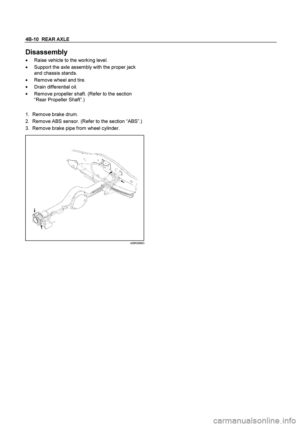
Disassembly
�
Raise vehicle to the working level.
�
Support the axle assembly with the proper jack
and chassis stands.
�
Remove wheel and tire.
�
Drain differential oil.
�
Remove propeller shaft. (Refer to the section
“Rear Propeller Shaft”.)
1.
Remove brake drum.
2. Remove ABS sensor. (Refer to the section “ABS”.)
3. Remove brake pipe from wheel cylinder.
420R300003
Page 176 of 4264

4B-12 REAR AXLE
Legend
1.
Offset Box Wrench
10.
Remove wheel cylinder.
11.
Remove bearing holder fixing nuts.
12.
Take out axle shaft assembly with back plate and
set it on a bench press as following illustration.
Put bolt head on thick steel plate.
When axle shaft is extracted, since axle case oil
seal is damaged, axle case oil seal.
13.
Remove snap ring. Use snap ring pliers to
remove. Snap ring is prohibition of reuse.
14.
Remove shim (If so equipped)
15.
Remove sensor rotor (or spacer), double tape
r
roller bearing, oil seal, bearing holder, and back
plate from axle shaft by means of a press.
�
Discard used oil seal, double taper roller
bearing, snap ring, ABS sensor rotor and
spacer.
A03R300002
Legend
1.
Bench Press Fitting
2. Steel Plate (25-30 mm thickness)
3. Axle Shaft
16. Remove differential assembly fixing bolts and
nuts and take out differential assembly.
17.
Remove wheel pin from axle shaft, using the
remover 5-8840-0079-0.
420L100009
18.
Remove axle case oil seal.
�
Discard used oil seal.
Page 178 of 4264
4B-14 REAR AXLE
Reassembly
1.
Using the oil seal installer 5-8840-2202-0, install
new axle case oil seal.
420R300004
Note :
Confirm that the dimention : A should be 34.5 –
36.1 mm (1.36 – 1.42 in)
A03R300004
2.
Install new oil seal in bearing holder, using the oil
seal installer 9-8522-1269-0.
F04R300002
Legend
1.
Oil Seal
2.
Bearing Holder
3.
Drive wheel pin into axle shaft flange, using a
hammer.
4.
Differential assembly
a.
Clean the mating surface of axle case and
differential carrier.
b.
Apply Three Bond 1215 (TB1215) or
equivalent on the surface of differential
assembly as flowing illustration.
425RS006
c. Tighten bolts and nuts to the specified torque.
Torque : Bolt
64 N�
m (6.5 kg�
m/47 lb�
ft)
Nut
44 N�
m (4.5 kg�
m/33 lb�
ft)
220 (8.66)
Rear axle type Banjo, semi-floating
Rear axle capacity N (kg/lb)16475 (1680/3700)
Rear axle case 16965")