Page 236 of 4264

4C1-16 FRONT WHEEL DRIVE
17. Support the differential case by the jack.
18. Remove the front axle mounting bolts and nuts, lower the
jack slowly. Remove the left side drive shaft end from the
knuckle, then lower the axle assembly from the vehicle.
CAUTION :
1. During the work, be sure that the axle assembly is
supported securly.
2. Be careful not to damage the bellows of the power
steering unit by interference.
3. Be careful not to damage the breater pipe and breater
pip bracket of the shift on the fly by interference.
Installation
1. Support the differential case by the jack.
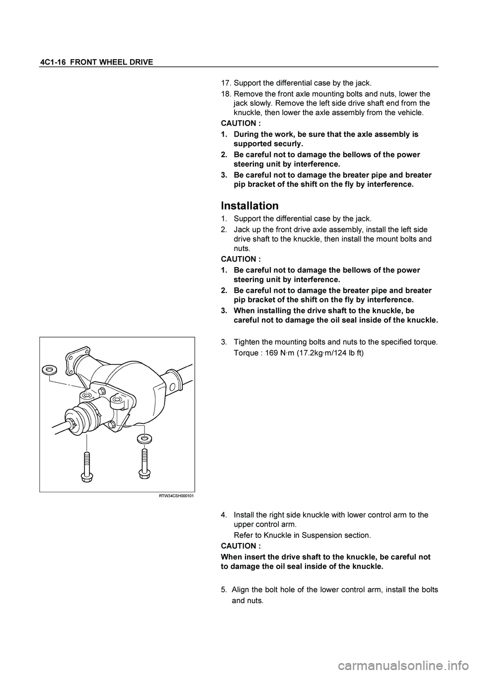
2. Jack up the front drive axle assembly, install the left side
drive shaft to the knuckle, then install the mount bolts and
nuts.
CAUTION :
1. Be careful not to damage the bellows of the power
steering unit by interference.
2. Be careful not to damage the breater pipe and breater
pip bracket of the shift on the fly by interference.
3. When installing the drive shaft to the knuckle, be
careful not to damage the oil seal inside of the knuckle.
RTW34CSH000101
3. Tighten the mounting bolts and nuts to the specified torque.
Torque : 169 N·m (17.2kg·m/124 lb ft)
4. Install the right side knuckle with lower control arm to the
upper control arm.
Refer to Knuckle in Suspension section.
CAUTION :
When insert the drive shaft to the knuckle, be careful not
to damage the oil seal inside of the knuckle.
5. Align the bolt hole of the lower control arm, install the bolts
and nuts.
Page 238 of 4264
4C1-18 FRONT WHEEL DRIVE
FRONT AXLE DRIVE SHAFT
Front Axle Drive Shaft and Associated Parts
RTW34CLF000401
Legend
1. Axle Case and Differential
2. Snap Ring
3. Bearing
4. Snap Ring
5. Oil Seal
6. Bracket
7. DOJ Case
8. Circlip
9. Bolt
10. Drive shaft Joint Assembly
11. Ball
12. Snap Ring
13. Ball Retainer
14. Ball Guide
15. Band
16. Bellows
17. Band
18. Band
19. Bellows
20. Band
21. UJ Shaft
22. Dust Seal
Page 244 of 4264
4C1-24 FRONT WHEEL DRIVE
DIFFERENTIAL
DISASSEMBLY
MAJOR COMPONENTS
RTW34CLF000501
Disassembly Steps
1. Bolt
2. Differential assembly
3. Axle case
4. Bolt
�
5. Bearing cap
6. Diff. cage assembly
�
7. Side bearing outer race
�
8. Side bearing
�
9. Adjust shims
�
10. Flange nut
11. Flange
12. Dust cover
�
13. Pinion gear
�
14. Inner bearing
15. Adjust shim
16. Collapsible spacer
�
17. Inner bearing outer race
18. Oil seal
19. Outer bearing
�
20. Outer bearing outer race
21. Diff. carrier
Page 245 of 4264
FRONT WHEEL DRIVE 4C1-25
Important Operations
5. Bearing Cap
Apply a setting mark to the side bearing cap and the differential
carrier.
7. Side Bearing Outer Race
After removal, keep the right and left hand side bearing
assemblies separate to maintain inner and outer race
combinations.
8. Side Bearing
Remover : 5-8840-0013-0
(J-22888)
Adapter : 9-8521-1743-0
(J-8107-2)
9. Adjust Shims
Note the thickness and position of the shims removed.
10. Flange Nut
Holding wrench : 5-8840-0133-0
(J-8614-01)
Page 247 of 4264
FRONT WHEEL DRIVE 4C1-27
MINOR COMPONENTS
Disassembly Steps
1. Bolt
2. Ring gear
�
3. Lock pin
�
4. Cross pin
5. Pinion gear
6. Side gear
7. Thrust washer
8. Differential cage
Page 249 of 4264

FRONT WHEEL DRIVE 4C1-29
INSPECTION AND REPAIR
Make all necessary adjustments, repairs, and part replacements if wear, damage, or other problems are discovered
during inspection.
� Ring gear, pinion gear
� Bearing
�
Side gear, pinion gear, cross pin
�
Differential cage, carrier
�
Thrust washer
�
Oil seal
Visual Check
Inspect the following parts for wear, damage, or other
abnormal conditions.
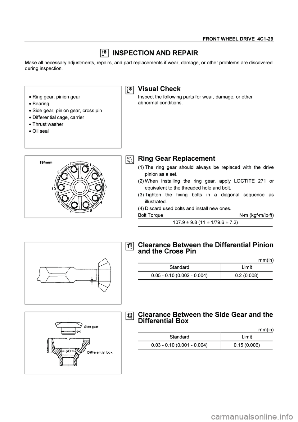
Ring Gear Replacement
(1) The ring gear should always be replaced with the drive
pinion as a set.
(2) When installing the ring gear, apply LOCTITE 271 o
r
equivalent to the threaded hole and bolt.
(3) Tighten the fixing bolts in a diagonal sequence as
illustrated.
(4) Discard used bolts and install new ones.
Bolt Torque N�m (kgf�m/lb�ft)
107.9 � 9.8 (11 � 1/79.6 � 7.2)
Clearance Between the Differential Pinion
and the Cross Pin
mm(in)
Standard Limit
0.05 - 0.10 (0.002 - 0.004) 0.2 (0.008)
Clearance Between the Side Gear and the
Differential Box
mm(in)
Standard Limit
0.03 - 0.10 (0.001 - 0.004) 0.15 (0.006)
Page 251 of 4264
FRONT WHEEL DRIVE 4C1-31
REASSEMBLY
MINOR COMPONENTS
Reassembly Steps
1. Differential cage
2. Thrust washer
3. Side gear
�
4. Pinion gear
�
5. Cross pin
�
6. Lock pin
�
7. Ring gear
�
8. Bolt
Important Operations
4. Pinion Gear
Install the pinion gear by engaging it with the side gears while
turning both pinion gears simultaneously in the same direction.
Page 252 of 4264
4C1-32 FRONT WHEEL DRIVE
5. Cross Pin
(1) Be sure to install the cross pin so that it is in alignment with
the lock pin hole in the differential cage.
(2)
Adjust the backlash between the side gear and the pinion
gear.
mm(in)
Backlash 0.10 - 0.20 (0.004 - 0.008)
Thickness of thrust washers available
mm(in)
1.00, 1.05, 1.10 (0.039, 0.041, 0.043)
6. Lock Pin
After lock pin installation, stake the cage to prevent discharge
of the lock pin.
7. Ring Gear
When installing the ring gear, apply LOCTITE 271 or
equivalent to the threaded hole and bolt.
8. Bolt
Tighten the bolts in diagonal sequence as illustrated.
Bolt Torque N�m (kgf�m/lb�ft)
107.9 � 9.8 (11 � 1/79.6 � 7.2)
Note :
Discard used bolts and install new ones.
Note that all bolts have a left hand thread.