Page 682 of 4264
8A-24 ELECTRICAL-BODY AND CHASSIS
MAIN DATA AND SPECIFICATIONS
BULB SPECIFICATIONS
This illustration based on LHD
RTW8AMF000501
Light Name Bulb No. Rated Power
V-W Number
of Bulbs Lens
Color Remarks
Headlight H4 12-60/55 2 White Halogen
High mounted stop light W5W 12-5 4 RED
Fog light H3 12-55 2 White
Front turn signal light PY21W 12-21 2 White Bulb Lens color
Amber
Clearance light W5W 12-5 2 White
Side turn signal light W5W 12-5 2 White with
amber
inner lens
Rear turn signal light PY21W 12-21 2 White Bulb Lens color
Amber
Rear fog light P21W 12-21 1 Red
Tail and stop light P21/5W 12-21/5 2 Red
Back up light P21W 12-21 2 White
License plate light W5W 12-5 2 White
A/C-Heater control light - 12-0.7 1 -
Dome light - 12-10 1 White
Spot light - 12-5 2 White
Page 683 of 4264
ELECTRICAL-BODY AND CHASSIS 8A-25
Light Name Rated Power
V-W Number of
Bulbs Lens
Color Remarks
W/O Tacho 5Illumination light 14-2
W/ Tacho 7White
Turn Signal 14-1.12 2 Green
High Beam 14-1.12 1 Blue
Low Fuel 14-1.12 1 Amber
A/T Oil Temp 14-1.12 1 Red
Brake system 14-1.12 1 Red
4WD 14-1.12 1 Green
Seat belt 14-1.12 1 Red
Oil pressure 14-1.12 1 Red
ABS 14-1.12 1 Amber
SEDIMENTER 14-1.12 1 Red
AIR BAG 14-1.12 1 Red
Brake 14-1.12 1 Red
Charge 14-1.12 1 Red
Check Trans 14-1.12 1 Red
Check 4WD 14-1.12 1 Red
Power drive 14-1.12 1 Amber
3rd start 14-1.12 1 Green
4L 14-1.12 1 Green
Cruise Set 14-1.12 1 Green
Check Engine 14-1.12 1 Amber
Front Fog 14-1.12 1 Green
Rear foglight 14-1. 12 1 Amber
Glow 14-1.12 1 Amber
P LED 1 Green
R LED 1 Green
N LED 1 Green
D LED 1 Green
3 LED 1 Green
2 LED 1 Green
Indicator/
Warning
light
A/T shift
indicator
L LED 1 Green
Page 827 of 4264

ELECTRICAL-BODY AND CHASSIS 8A-169
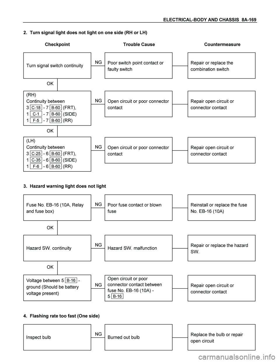
2. Turn signal light does not light on one side (RH or LH)
Checkpoint Trouble Cause Countermeasure
Repair open circuit or
connector contact
Open circuit or poor connector
contact
NG
(LH)
Continuity between
3
C-25 - 6 B-60 (FRT),
1
C-35 - 6 B-60 (SIDE)
1
F-6 - 6 B-60 (RR)
(RH)
Continuity between
3
C-18 - 7 B-60 (FRT),
1
C-1 - 7 B-60 (SIDE)
1
F-5 - 7 B-60 (RR)
Repair or replace the
combination switch
Turn signal switch continuity
Poor switch point contact or
faulty switch
NG
OK OK
Repair open circuit or
connector contact
Open circuit or poor connector
contact
NG
3. Hazard warning light does not light
Repair or replace the hazard
SW.
Hazard SW. malfunction
NG
Voltage between 5 B-16 -
ground (Should be battery
voltage present)
Hazard SW. continuity
Reinstall or replace the fuse
No. EB-16 (10A)
Fuse No. EB-16 (10A, Relay
and fuse box)
Poor fuse contact or blown
fuse
NG
OK OK
Repair open circuit or
connector contact
Open circuit or poor
connector contact between
fuse No. EB-16 (10A) -
5
B-16 NG
4. Flashing rate too fast (One side)
Replace the bulb or repair
open circuitInspect bulbBurned out bulb NG
Page 832 of 4264

8A-174 ELECTRICAL-BODY AND CHASSIS
Installation
Follow the removal procedure in the reverse order to install the
rear combination light.
Pay close attention to the important points mentioned in the
following paragraphs.
Bulb
Be absolutely sure that each bulb is correctly installed.
This will prevent a poor contact and an open circuit.
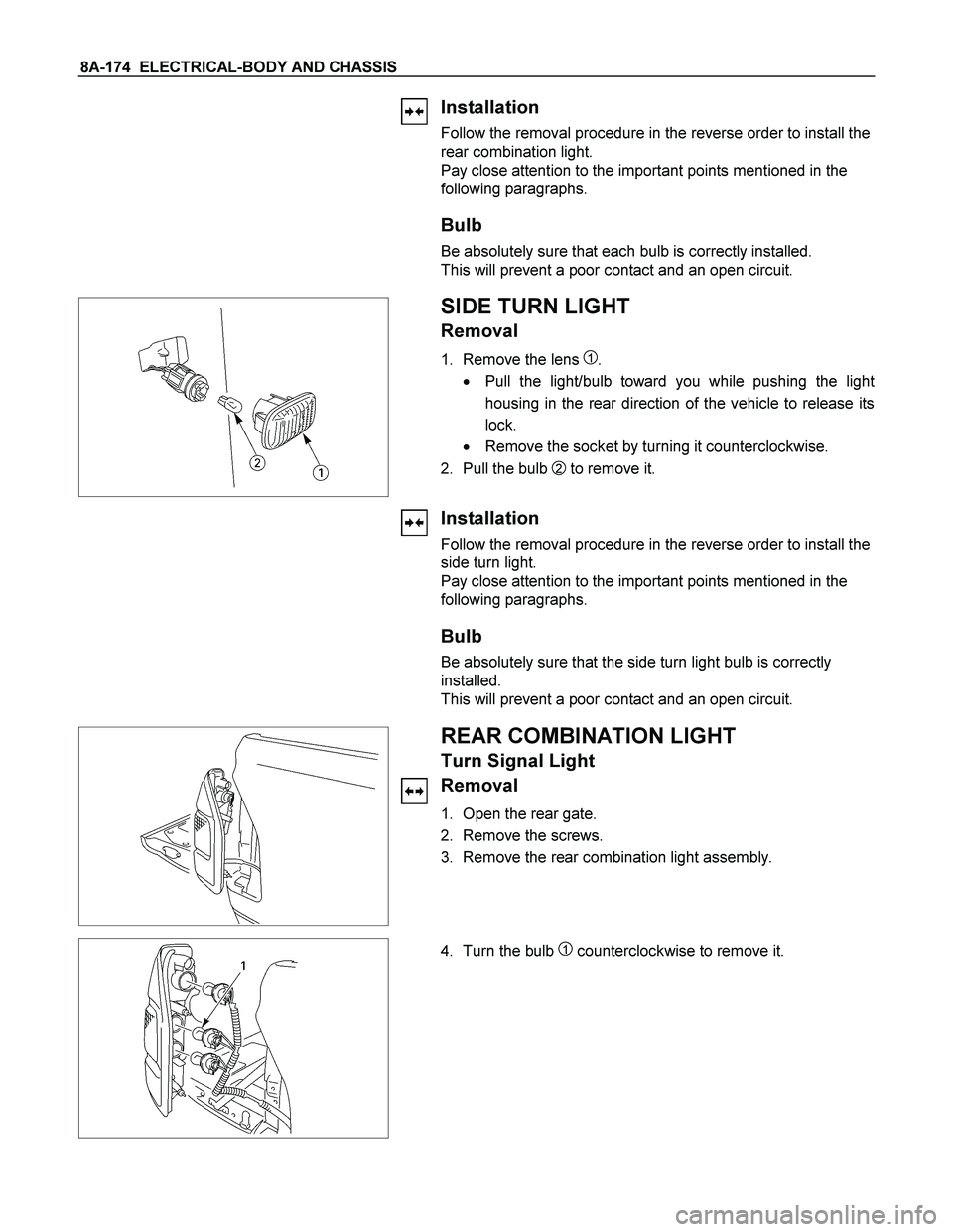
SIDE TURN LIGHT
Removal
1. Remove the lens 1.
� Pull the light/bulb toward you while pushing the ligh
t
housing in the rear direction of the vehicle to release its
lock.
� Remove the socket by turning it counterclockwise.
2. Pull the bulb
2 to remove it.
Installation
Follow the removal procedure in the reverse order to install the
side turn light.
Pay close attention to the important points mentioned in the
following paragraphs.
Bulb
Be absolutely sure that the side turn light bulb is correctly
installed.
This will prevent a poor contact and an open circuit.
REAR COMBINATION LIGHT
Turn Signal Light
Removal
1. Open the rear gate.
2. Remove the screws.
3. Remove the rear combination light assembly.
4. Turn the bulb 1 counterclockwise to remove it.