Page 260 of 4264
4C1-40 FRONT WHEEL DRIVE
18. Bolt
Bolt Torque N�
m (kgf�
m/lb�
ft)
98.1 � 9.8 (10.0 � 1.0/72.3 � 7.2)
Measure the amount of run-out of the ring gear at its rear face.
mm(in)
Standard Limit
0.02 (0.001) 0.05 (0.002)
Gear Tooth Contact Pattern Check and Adjustment
Apply a thin coat of prussian blue or equivalent to the faces of
the 7 - 8 teeth of the ring gear. Check the impression of
contact on the ring gear teeth and make necessary adjustment
as described below if the contact is abnormal.
Page 1132 of 4264
6 – 12 TROUBLESHOOTING
10. Abnormal Engine Noise
10–1 Engine knocking
Step Action Value(s) Yes No
1 Was the injection nozzle pressure or injection spray
pattern OK? —
Go to Step 2 Replace the
injection nozzle
2 Was the compression pressure OK? 3.0 MPa
(31.0 kg/cm2,
441 psi) at
200 rpm Go to Step 3 Replace the
cylinder head
gasket or
piston ring
3 Are any DTC stored? — Go to indicated
DTC Solved
10–2 Gas leakage noise
Step Action Value(s) Yes No
1 Was the exhaust pipe loose or broken? — Retighten or
replace the
exhaust pipe Go to Step 2
2 Was the exhaust manifold loose? — Retighten or
replace the
exhaust
manifold. Or
replace the
exhaust
manifold
gasket Go to Step 3
3 Was the injection nozzle loose? — Retighten or
replace the
injection nozzle
fixing bolt Go to Step 4
4 Was the cylinder head gasket broken? — Replace the
cylinder head
gasket Go to Step 5
5 Are any DTC stored? — Go to indicated
DTC Solved
Page 2455 of 4264

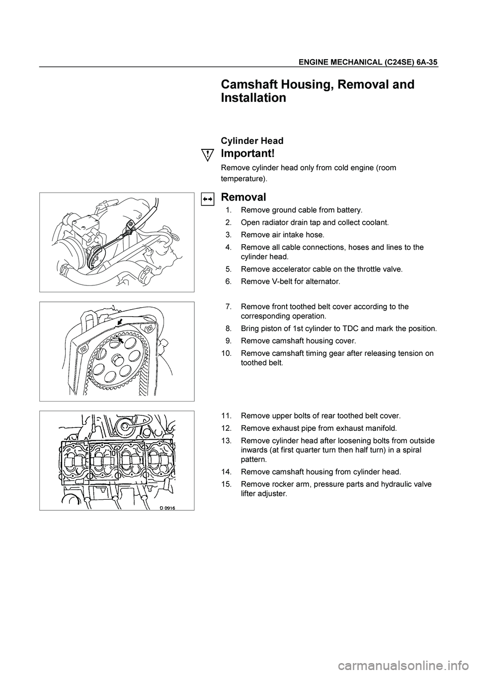
ENGINE MECHANICAL (C24SE) 6A-35
Camshaft Housing, Removal and
Installation
Cylinder Head
Important!
Remove cylinder head only from cold engine (room
temperature).
Removal
1. Remove ground cable from battery.
2. Open radiator drain tap and collect coolant.
3. Remove air intake hose.
4. Remove all cable connections, hoses and lines to the
cylinder head.
5. Remove accelerator cable on the throttle valve.
6. Remove V-belt for alternator.
7. Remove front toothed belt cover according to the
corresponding operation.
8. Bring piston of 1st cylinder to TDC and mark the position.
9. Remove camshaft housing cover.
10. Remove camshaft timing gear after releasing tension on
toothed belt.
11. Remove upper bolts of rear toothed belt cover.
12. Remove exhaust pipe from exhaust manifold.
13. Remove cylinder head after loosening bolts from outside
inwards (at first quarter turn then half turn) in a spiral
pattern.
14. Remove camshaft housing from cylinder head.
15. Remove rocker arm, pressure parts and hydraulic valve
lifter adjuster.
Page 2456 of 4264

6A-36 ENGINE MECHANICAL (C24SE)
Clean
All sealing surfaces, drill holes in cylinder head bolts.
Check cylinder block and cylinder head for plane surface
according to the corresponding operations.
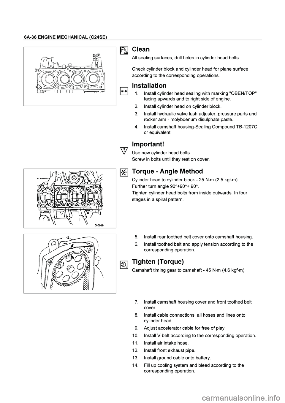
Installation
1. Install cylinder head sealing with marking "OBEN/TOP"
facing upwards and to right side of engine.
2. Install cylinder head on cylinder block.
3. Install hydraulic valve lash adjuster, pressure parts and
rocker arm - molybdenum disulphate paste.
4. Install camshaft housing-Sealing Compound TB-1207C
or equivalent.
Important!
Use new cylinder head bolts.
Screw in bolts until they rest on cover.
Torque - Angle Method
Cylinder head to cylinder block - 25 N�
m (2.5 kgf�
m)
Further turn angle 90�
+90�
+ 90�
.
Tighten cylinder head bolts from inside outwards. In four
stages in a spiral pattern.
5. Install rear toothed belt cover onto camshaft housing.
6. Install toothed belt and apply tension according to the
corresponding operation.
Tighten (Torque)
Camshaft timing gear to camshaft - 45 N�
m (4.6 kgf�
m)
7. Install camshaft housing cover and front toothed belt
cover.
8. Install cable connections, all hoses and lines onto
cylinder head.
9. Adjust accelerator cable for free of play.
10. Install V-belt according to the corresponding operation.
11. Install air intake hose.
12. Install front exhaust pipe.
13. Install ground cable onto battery.
14. Fill up cooling system and bleed according to the
corresponding operation.
Page 2466 of 4264
6A-46 ENGINE MECHANICAL (C24SE)
Inspection
Check contact pattern (I
) on valve seat and in cylinder head.
Clean
Valves, valve guides, cylinder head.
Flywheel
Removal
1. Remove transmission and clutch.
2. Remove flywheel while locking with 5-88400-446-0.
Torque - Angle Method
Flywheel to crankshaft - 65 Nm/6.5 kgf�
m.+30�
to 45�
Important!
Use new bolts.
Do not apply grease to the thread.
Installation
1. Install clutch and transmission.
Component Parts
Flywheel and Ring gear. (Manual Transmission)
Page 3448 of 4264

3B-18 POWER-ASSISTED STEERING SYSTEM
Disassembly
1. Clean the oil pump with solvent (plug the discharge
and suction ports to prevent the entry of solvent).
Be careful not to expose the oil seal of shaf
t
assembly to solvent.
2. Remove the bolt, suction pipe and O-ring.
3. Remove the connector, O-ring, relief valve and
spring.
4. Remove the bolt, rear housing and O-ring.
5. Remove the snap ring.
6. Remove the shaft assembly.
7. Remove the oil seal.
CAUTION: When removing the oil seal, be careful
not to damage the housing.
8. Remove the pump cartridge assembly from the fron
t
housing.
9. Remove two O-rings.
Inspection and Repair
Make all necessary adjustments, repairs, and part
replacements if wear, damage, or other problems are
discovered during inspection.
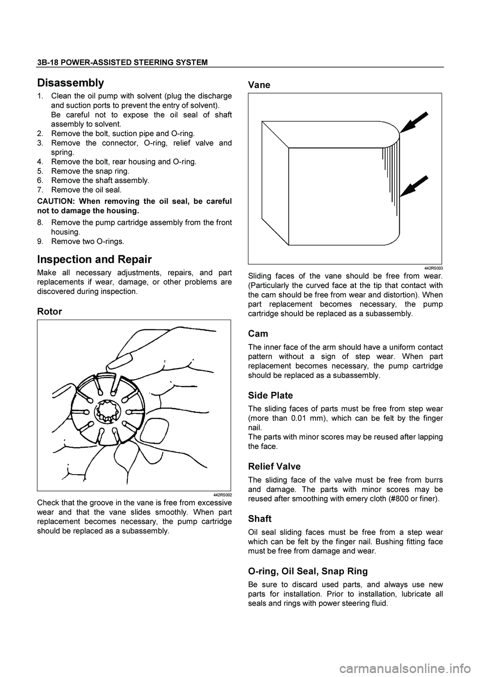
Rotor
442RS002
Check that the groove in the vane is free from excessive
wear and that the vane slides smoothly. When par
t
replacement becomes necessary, the pump cartridge
should be replaced as a subassembly.
Vane
442RS003
Sliding faces of the vane should be free from wear.
(Particularly the curved face at the tip that contact with
the cam should be free from wear and distortion). When
part replacement becomes necessary, the pump
cartridge should be replaced as a subassembly.
Cam
The inner face of the arm should have a uniform contact
pattern without a sign of step wear. When part
replacement becomes necessary, the pump cartridge
should be replaced as a subassembly.
Side Plate
The sliding faces of parts must be free from step wear
(more than 0.01 mm), which can be felt by the finge
r
nail.
The parts with minor scores may be reused after lapping
the face.
Relief Valve
The sliding face of the valve must be free from burrs
and damage. The parts with minor scores may be
reused after smoothing with emery cloth (#800 or finer).
Shaft
Oil seal sliding faces must be free from a step wear
which can be felt by the finger nail. Bushing fitting face
must be free from damage and wear.
O-ring, Oil Seal, Snap Ring
Be sure to discard used parts, and always use new
parts for installation. Prior to installation, lubricate all
seals and rings with power steering fluid.
Page 3453 of 4264

POWER-ASSISTED STEERING SYSTEM 3B-23
Disassembly
1. Clean the oil pump with solvent (plug the discharge
and suction ports to prevent the entry of solvent). Be
careful not to expose the oil seal of shaft assembl
y
to solvent.
2. Remove the bolt, suction pipe and O-ring.
Remove the O-ring.
3. Remove the connector, O-ring, relief valve and
spring.
4. Remove the pressure switch assembly.
5. Remove the bolt, rear housing and O-ring.
6. Remove the snap ring.
7. Remove the shaft assembly.
8. Remove the oil seal.
CAUTION: When removing the oil seal, be careful
not to damage the housing.
9. Remove the pump cartridge assembly from the fron
t
housing.
10. Remove two O-rings.
Inspection and Repair
Make all necessary adjustments, repairs, and part
replacements if wear, damage, or other problems are
discovered during inspection.
Rotor
442RS002
Check that the groove in the vane is free from excessive
wear and that the vane slides smoothly. When part
replacement becomes necessary, the pump cartridge
should be replaced as a subassembly.
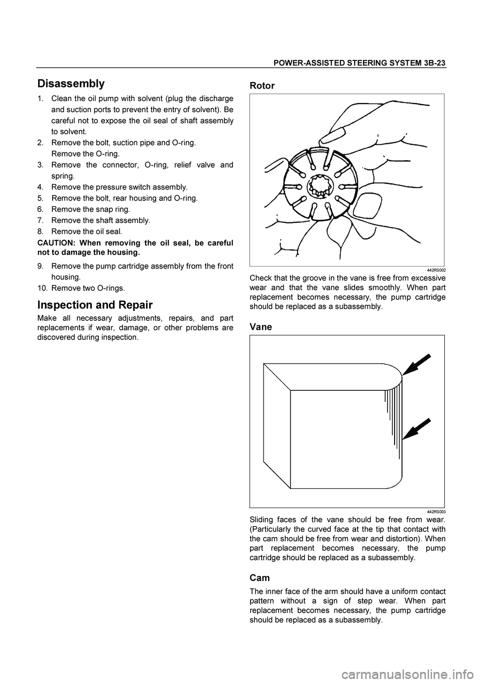
Vane
442RS003
Sliding faces of the vane should be free from wear.
(Particularly the curved face at the tip that contact with
the cam should be free from wear and distortion). When
part replacement becomes necessary, the pump
cartridge should be replaced as a subassembly.
Cam
The inner face of the arm should have a uniform contact
pattern without a sign of step wear. When part
replacement becomes necessary, the pump cartridge
should be replaced as a subassembly.