Page 538 of 4264
10-30 CAB
12. Instrument Panel & Cross Beam Assembly
1) Remove the two bolts fixing the steering column to the
cross beam and the two bolts fixing the brake pedal
bracket to the cross beam.
2) Remove the two bolts fixing the parking brake bracket to
the cross beam (Stick type parking brake only).
3) Disconnect the control cables at the blower unit and
heater unit.
Remove the front & side cover from the instrumen
t
panel.
4) Remove the fasteners fixing the instrument panel &
cross beam assembly to the body panel.
5) Disconnect the instrument harness connectors.
Page 660 of 4264

8A-2 ELECTRICAL-BODY AND CHASSIS
PAGE
Fuse and Slow Blow Fuse Location (Relay and Fuse Box) .................................... 8A- 31
Fuse Location ............................................................................................................. 8A- 33
Diode Location ........................................................................................................... 8A- 34
Fuse Block Circuit ...................................................................................................... 8A- 35
Fuse Block Circuit (C24SE) ....................................................................................... 8A- 35
Fuse Block Circuit (6VE1) ......................................................................................... 8A- 37
Fuse Block Circuit (4JA1-TC/4JH1-TC) - RHD ......................................................... 8A- 39
Fuse Block Circuit (4JA1-TC/4JH1-TC) – LHD ......................................................... 8A- 41
Fuse Block Circuit (4JH1-L) ...................................................................................... 8A- 43
Grounding Point ............................................................................................................. 8A- 45
Ground Point .............................................................................................................. 8A- 45
Ground Point Location .............................................................................................. 8A- 61
Main Cable harness Routing .......................................................................................... 8A- 63
C24SE / 6VE1 / 4JA1-L / 4JH1-TC .............................................................................. 8A- 63
Instrument Harness .................................................................................................... 8A- 71
System Repair .................................................................................................................8A- 73
Start and Charging ..................................................................................................... 8A- 73
Engine Control Module (ECM) ................................................................................... 8A- 89
Exhaust Gas Recalculation (EGR): 4JA1-L Only ...................................................... 8A- 109
Lighting ....................................................................................................................... 8A- 114
Front Fog Light ........................................................................................................... 8A- 136
Rear Fog Light ............................................................................................................ 8A- 144
Head Light Leveling ................................................................................................... 8A- 149
Illumination ................................................................................................................. 8A- 154
Hazard Warning Flasher, Turn Signal Light, Back Up Light,
Horn and Stop Light ................................................................................................. 8A- 161
Dome Light, Spot Light and Warning Buzzer .......................................................... 8A- 181
Windshield Wiper and Washer .................................................................................. 8A- 196
Transmission Control Module (TCM) ....................................................................... 8A- 214
Meter, Warning Light and Indicator Light ................................................................ 8A- 223
Heater and Air Conditioning ...................................................................................... 8A- 281
Power Door Lock ....................................................................................................... 8A- 293
Page 682 of 4264
8A-24 ELECTRICAL-BODY AND CHASSIS
MAIN DATA AND SPECIFICATIONS
BULB SPECIFICATIONS
This illustration based on LHD
RTW8AMF000501
Light Name Bulb No. Rated Power
V-W Number
of Bulbs Lens
Color Remarks
Headlight H4 12-60/55 2 White Halogen
High mounted stop light W5W 12-5 4 RED
Fog light H3 12-55 2 White
Front turn signal light PY21W 12-21 2 White Bulb Lens color
Amber
Clearance light W5W 12-5 2 White
Side turn signal light W5W 12-5 2 White with
amber
inner lens
Rear turn signal light PY21W 12-21 2 White Bulb Lens color
Amber
Rear fog light P21W 12-21 1 Red
Tail and stop light P21/5W 12-21/5 2 Red
Back up light P21W 12-21 2 White
License plate light W5W 12-5 2 White
A/C-Heater control light - 12-0.7 1 -
Dome light - 12-10 1 White
Spot light - 12-5 2 White
Page 686 of 4264
8A-28 ELECTRICAL-BODY AND CHASSIS
RELAY LOCATION (RELAY AND FUSE BOX)
RELAY & FUSE BOX
RHD
NO. RELAY (C24SE) RELAY (6VE1) RELAY
(4JA1-TC/4JH1-TC)RELAY (4JA1-L)
X-1 RELAY; TAIL LIGHT
� � �
X-2 RELAY; FUEL PUMP
� RELAY; FRT FOG RELAY; FRT FOG
LIGHT
X-3 RELAY; HORN
� � �
X-4 RELAY; DIMMER
� � �
X-5 RELAY; FOG LIGHT
� RELAY; GLOW RELAY; GLOW
X-6 RELAY; STARTER
� RELAY; COND, FAN RELAY; CSD
X-7 RELAY; COND, FAN
� RELAY; RR FOG
�
X-8
� � RELAY; STARTER RELAY; STARTER
X-9 RELAY; HAZARD-RH
� � �
X-10 RELAY; HAZARD-LH
� � �
X-11 RELAY; HEATER
� � �
X-12 RELAY; HEAD
LIGHT � � �
X-13
� RELAY; ECM MAIN
� RELAY; COND, FAN
X-14 RELAY; A/C COMP
� � �
X-15 RELAY; THERMO
� � �
Page 687 of 4264
ELECTRICAL-BODY AND CHASSIS 8A-29
RELAY LOCATION (RELAY AND FUSE BOX)
RELAY & FUSE BOX
LHD
NO. RELAY (C24SE) RELAY (6VE1) RELAY
(4JA1-TC 4JH1-TC)RELAY (4JA1-L)
X-1 RELAY; TAIL LIGHT
� � �
X-2 RELAY; FUEL PUMP
� RELAY; FRT FOG RELAY; FRT FOG
LIGHT
X-3 RELAY; HORN
� � �
X-4 RELAY; DIMMER
� � �
X-5 RELAY; FRT FOG
LIGHT RELAY; FOG LIGHT RELAY; GLOW RELAY; GLOW
X-6 RELAY; STARTER
� RELAY; COND, FAN RELAY; CSD
X-7 RELAY; COND, FAN
� RELAY; RR FOG
�
X-8
� � RELAY; STARTER
�
X-9
� � SHORT
CONNECTOR
(with cooler) �
X-10
� � � �
X-11 RELAY; HEATER
� � �
X-12 RELAY; HEAD
LIGHT � � �
X-13
� RELAY; ECM MAIN
� RELAY; COND, FAN
X-14 RELAY; A/C COMP
� � �
X-15 RELAY; THERMO
� � �
Page 939 of 4264
ELECTRICAL-BODY AND CHASSIS 8A-281
HEATER AND AIR CONDITIONING
PARTS LOCATION (RHD)
RTW48AXF018801 & RTW48AXF018901
Page 1098 of 4264
8A-440 ELECTRICAL-BODY AND CHASSIS
No. Connector face No. Connector face
X-1
Black
Relay ; Tail lamp X-8
(4JH1-TC)
BlackRelay ; Starter
X-2
(C24SE)
(6VE1)
Black Relay ; Front Fog lamp X-9
(6VE1)
(4JH1-TC)
BlackRelay ; Hazard-RH
X-2
(4JH1-TC)
Black Relay ; Front Fog lamp X-10
(6VE1)
(4JH1-TC)
BlackRelay ; Hazard-LH
X-3
Relay ; Horn X-11
BlackRelay ; Heater
X-4
Relay ; Dimmer X-12
BlackRelay ; Head lamp
X-5
(6VE1)
Black Relay ; Front Fog Lamp X-13
(6VE1)
(4JH1-TC)
BlackRelay ; ECM MAIN
X-5
(4JH1-TC)
Black Relay ; Spill valve X-14
BlackRelay ; A/C Compressor
X-6
(C24SE)
(6VE1)
Relay ; Starter X-15
BlackRelay ; Thermo
X-6
(4JA1-L)
Black Relay ; CSD X-16
(6VE1)
(4JH1-TC)
BlackDIODE
X-7
Relay ; Condenser Fan X-17
BlackDIODE
Page 1167 of 4264

ENGINE MECHANICAL 6A – 27
111R300001
COOLING SYSTEM
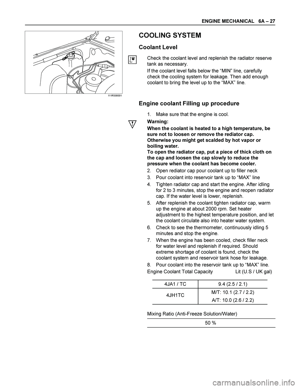
Coolant Level
Check the coolant level and replenish the radiator reserve
tank as necessary.
If the coolant level falls below the “MIN” line, carefully
check the cooling system for leakage. Then add enough
coolant to bring the level up to the “MAX” line.
Engine coolant Filling up procedure
1. Make sure that the engine is cool.
Warning:
When the coolant is heated to a high temperature, be
sure not to loosen or remove the rediator cap.
Otherwise you might get scalded by hot vapor or
boiling water.
To open the radiator cap, put a piece of thick cloth on
the cap and loosen the cap slowly to reduce the
pressure when the coolant has become cooler.
2. Open rediator cap pour coolant up to filler neck
3. Pour coolant into reservoir tank up to “MAX” line
4. Tighten radiator cap and start the engine. After idling
for 2 to 3 minutes, stop the engine and reopen radiator
cap. If the water level is lower, replenish.
5. After replenish the coolant tighten radiator cap, warm
up the engine at about 2000 rpm. Set heater
adjustment to the highest temperature position, and let
the coolant circulate also into heater water system.
6. Check to see the thermometer, continuously idling 5
minutes and stop the engine.
7. When the engine has been cooled, check filler neck
for water level and replenish if required. Should
extreme shortage of coolant is found, check the
coolant system and reservoir tank hose for leakage.
8. Pour coolant into the reservoir tank up to “MAX” line.
Engine Coolant Total Capacity Lit (U.S / UK gal)
4JA1 / TC 9.4 (2.5 / 2.1)
4JH1TC M/T: 10.1 (2.7 / 2.2)
A/T: 10.0 (2.6 / 2.2)
Mixing Ratio (Anti-Freeze Solution/Water)
50 %