Page 384 of 4264
 Tire Diameter Error
Step Action
Value(s) Yes No
1 Was the “Basic Diagnostic Flow Chart” performed?
- Go to Step 2 Go to Basic
Diag")
5A-68 BRAKE CONTROL SYSTEM
DTC C0238 (Flash Code 38) Tire Diameter Error
Step Action
Value(s) Yes No
1 Was the “Basic Diagnostic Flow Chart” performed?
- Go to Step 2 Go to Basic
Diagnostic
Flow Chart
2 1. Check for the tire size of each wheels.
2. If the tire size is different, replace the tire.
3. If a problem is found, repair as necessary.
Was a problem found?
- Verify repair Go to Step 3
3 1. Check for the gear ratio of a front axle differential
gear and a rear axle differential gear.
2. If the gear ratio is different, repair the gear ratio.
3. If a problem is found, repair as necessary.
Was a problem found?
- Verify repair Go to Step 4
4 Select “Display DTCs” with the Tech 2.
Note : Perform the various tests (actuator test, test
run, brake test, etc.) then observe the DTC with a
Tech2.
Are any DTCs stored? - Go to Step 5 Verify repair
5 Replace EHCU.
Note : Check the EHCU type for specification, when
the EHCU is replaced.
(Specification ; 2WD model or 4WD model)
Was the action complete? - Verify repair -
Page 453 of 4264

BRAKES 5C-27
15. Repeat steps 12 through 14 until no air comes out of the
port when the brake pipe is loosened
NOTE : Be very careful not to allow the brake fluid to come in
contact with painted surfaces.
16. Bleed the air from the front wheel brake pipe connection (2)
by repeating steps 6 through 15.
Bleeding the Caliper
17. Bleed the air from each wheel in the order listed below:
�
Right rear wheel cylinder
�
Left rear wheel cylinder
�
Left front caliper
� Right front caliper
Conduct air bleeding from the wheels in the above order. I
f
no brake fluid comes out, it suggests that air is mixed in the
master cylinder. In this case, bleed air from the maste
r
cylinder. In this case, bleed air from the master cylinder in
accordance with steps 6 through 16, and then bleed ai
r
from the caliper or wheel cylinder.
RTW35CSH000501
18. Place the proper size box end wrench over the bleeder
screw.
19. Cover the bleeder screw with a transparent tube, and
submerge the free end of the transparent tube in a
transparent container containing brake fluid.
5042
20. Pump the brake pedal slowly three (3) times (once/sec),
then hold it depressed.
21. Loosen the bleeder screw until fluid flows through the tube.
22. Retighten the bleeder screw.
23. Release the brake pedal slowly.
24. Repeat steps 21 through 24 until the air is completel
y
removed.
It may be necessary to repeat the bleeding procedure 10 o
r
more times for front wheels and 15 or more times for rear
wheels.
25. Go to the next wheel in the sequence after each wheel is
bled.
Be sure to monitor reservoir fluid level.
26. Depress the brake pedal to check if you feel “sponginess"
after the air has been removed from all wheel cylinders and
calipers.
If the pedal feels “spongy", the entire bleeding procedure
must be repeated.
Page 2414 of 4264

Condition Possible cause Correction
Engine overheating Level of Engine Coolant too low Replenish
Thermo switch or fan motor
defective Replace
Thermostat defectiv")
6-8 ENGINE DIAGNOSIS (C24SE)
Condition Possible cause Correction
Engine overheating Level of Engine Coolant too low Replenish
Thermo switch or fan motor
defective Replace
Thermostat defective Replace
Engine Coolant pump defective Correct or replace
Radiator clogged Clean or replace
Radiator filter cap defective Replace
Level of oil in engine crankcase
too low or wrong oil in engine Change or replenish
Resistance in exhaust system
increased Clean exhaust system or replace
defective parts
Throttle Position Sensor
adjustment incorrect Adjust Wide Open Throttle switch
setting
Throttle Position Sensor circuit
open or shorted Correct or replace
Cylinder head gasket damaged Replace
Cooling Fan clutch defective Replace
Fan belt slipping Adjust tension of V-belt or replace
V-belt
Engine overcooling Thermostat defective Replace (Use a thermostat set to
open at 92�C (197.6�F))
Engine lacks compression - Refer to Hard Start
Others Tire inflation pressure abnormal Adjust to recommend pressures
Brake drag Adjust
Clutch slipping Adjust or replace
Level of oil in engine crankcase
too high Correct level of engine oil
Engine Noisy
Abnormal engine noise often consists of various
noises originating in rotating parts, sliding parts and
other moving parts of the engine. It is, therefore,
advisable to locate the source of noise systematically.
Condition Possible cause Correction
Noise from crank journals or from
crank bearings
(Faulty crank journals and crank
bearings usually make dull noise
that becomes more evident when
accelerating) Oil clearance increased due to
worn crank journals or crank
bearings Replace crank bearings and
crankshaft or regrind crankshaft
and install the over size bearing
Crankshaft out of round Replace crank bearings and
crankshaft or regrind crankshaft
and install the over size bearing
Crank bearing seized Replace crank bearings and
crankshaft or regrind crankshaft
and install the over size bearing
Page 3574 of 4264
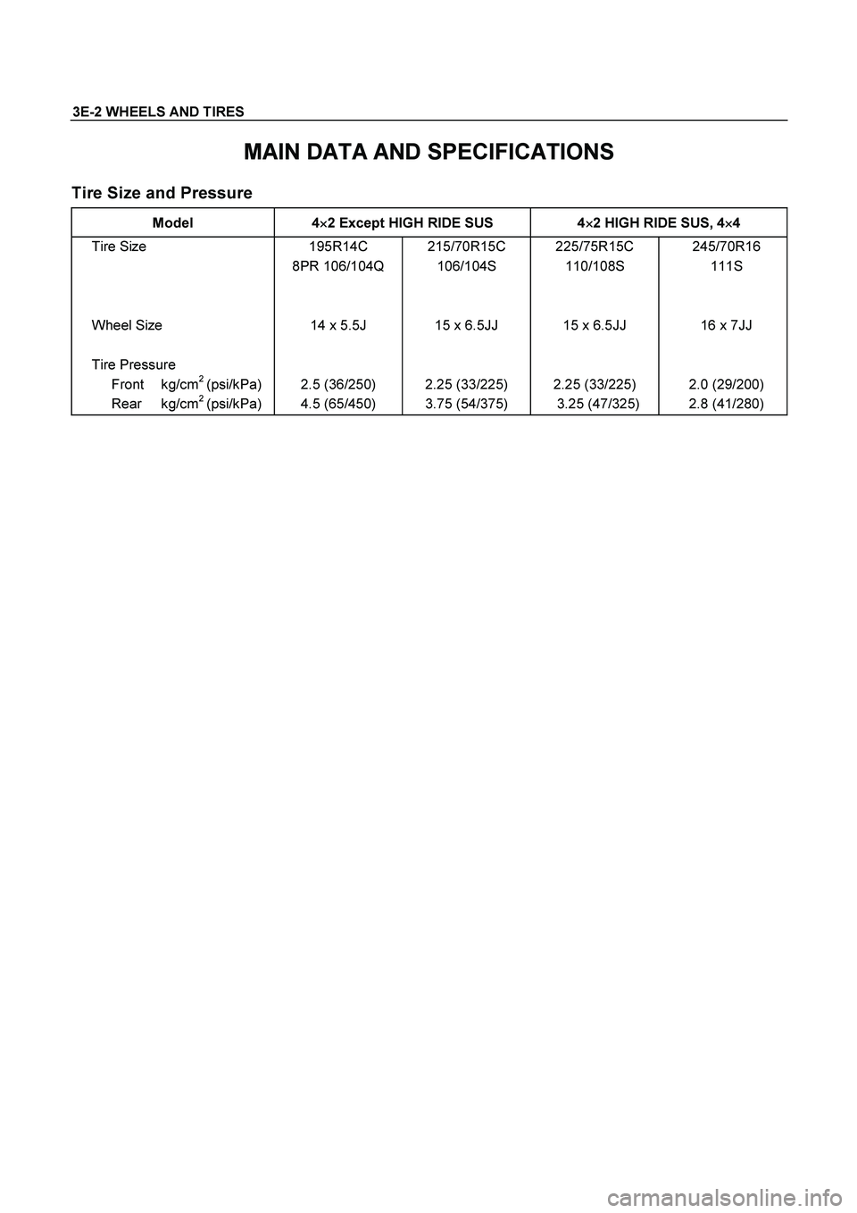
3E-2 WHEELS AND TIRES
MAIN DATA AND SPECIFICATIONS
Tire Size and Pressure
Model 4�
�� �2 Except HIGH RIDE SUS 4�
�� �2 HIGH RIDE SUS, 4�
�� �4
Tire Size
Wheel Size
Tire Pressure
Front
kg/cm
2 (psi/kPa)
Rear
kg/cm2 (psi/kPa)195R14C
8PR 106/104Q
14 x 5.5J
2.5 (36/250)
4.5 (65/450) 215/70R15C
106/104S
15 x 6.5JJ
2.25 (33/225)
3.75 (54/375) 225/75R15C
110/108S
15 x 6.5JJ
2.25 (33/225)
3.25 (47/325) 245/70R16
111S
16 x 7JJ
2.0 (29/200)
2.8 (41/280)