Page 239 of 4264
FRONT WHEEL DRIVE 4C1-19
Disassembly
NOTE :
For the left side, follow the same steps as right side.
1. Use a hammer and chisel to remove the 3 pawls (above
the large and small boot bands on the DOJ side).
COUTION :
Take care not to damage the bellows during band removal.
2. Remove band (1).
3. Pry off circlip (1) with a screwdriver or equivalent.
4. Remove drive shaft joint assembly.
5. Remove the six balls (1) with a screwdriver or equivalent.
Page 240 of 4264
4C1-20 FRONT WHEEL DRIVE
6. Using snap ring pliers, remove the snap ring (1) fastening
the ball retainer to the center shaft.
7. Remove ball retainer, ball guide and bellows.
8. Use a hammer and chisel to remove the 3 pawls (above
the large and small boot bands on the UJ side).
CAUTION :
Take care not to damage the bellows during band removal.
9. Remove band (1).
10. Remove bellows.
11. Remove dust seal from UJ.
12. Remove UJ shaft assembly.
13. Remove the mounting bracket fixing bolts, and then
remove DOJ case assembly from the axle case.
14. Remove snap ring and bearing.
15. Remove snap ring and oil seal.
16. Remove bracket.
Inspection And Repair
Make necessary correction or parts replacement if wear,
damage, corrosion or any other abnormal condition are found
through inspection.
Check the following parts.
1. Drive shaft joint assembly
2. DOJ case, ball, ball guide, ball retainer
3. Bellows
4. Bearing
5. Dust seal, oil seal
Page 467 of 4264
BRAKES 5C-41
Thickness of Disc Pad
Thickness (t) mm(in)
Standard Limit
10.0 (0.394) 1.8 (0.071)
Replace the front disc pad whenever the pad wear indicator
makes a squeaking noise or when the pad is worn to within 1.8
mm of the shoe table.
All four brake pads should be replaced together.
302R300019
Seal and Boot
The dust seal, dust boot and ring seal are to be replaced each
time the caliper is overhauled.
Discard thee used rubber parts.
Page 470 of 4264
5C-44 BRAKES
REAR DRUM BRAKE ASSEMBLY
DISASSEMBLY
First, disassemble the brake drum. Then disassemble the rear brake assembly.
Refer to the “REAR AXLE ” section for the brake drum disassembly procedure.
RTW35CMF000201
MAJOR COMPONENTS
Disassembly Steps
1. Spring ; adjuster
2. Ring ; Adjuster lever
3. Lever ; adjuster
� 4. Spring ; Shoe hold
5. Pin ; Shoe hold
� 6. Spring ; Shoe to shoe, lower
7. Adjuster assembly
8. Spring ; shoe to shoe, upper
9. Shoe ; leading
10. Shoe ; trailing
11. Spring ; lever return
12. Retainer
13. Washer ; lever
14. Lever ; parking
15. Bolt ; wheel cylinder
16. Wheel cylinder assembly
17. Cover
18. Back plate
MINOR COMPONENTS
Disassembly Steps
Wheel Cylinder Assembly (14)
19. Piston
20. Cup
21. Boot ; piston
22. Return spring
23. Bleeder
24. Cap ; bleeder
Page 473 of 4264
BRAKES 5C-47
REASSEMBLY
RTW35CMF000301
MINOR COMPONENTS
Reassembly Steps
Wheel cylinder Assembly (7)
1. Piston assembly
2. Cup ; piston
3. Return spring
�
4. Boot ; piston
� 5. Bleeder
6. Cap ; bleeder
MAJOR COMPONENTS
Reassembly Steps
7. Back plate
8. Cover
� 9. Wheel cylinder assembly
� 10. Bolt ; wheel cylinder
� 11. Shoe ; leading
� 12. Lever ; parking
� 13. Washer ; lever
� 14. Retainer
15. Spring ; lever return
�
16. Shoe ; trailing
� 17. Spring ; shoe to shoe, upper
� 18. Adjust assembly
19. Spring ; shoe to shoe ; lower
� 20. Lever ; adjuster
� 21. Ring ; Adjuster lever
22. Spring ; shoe hold
� 23. Pin ; shoe hold
� 24. spring ; adjuster
Page 474 of 4264
5C-48 BRAKES
Important Operations
Note :
�
Wash the disassembled parts in clean brake fluid.
�
Use compressed air to clean the ports.
�
Protect the disassembled part surfaces from dust and othe
r
foreign material contamination.
�
Before reassembly, check the part surfaces for dust and
other foreign material contamination.
�
Be sure to replace the designated parts with new ones.
4. Piston Assembly
Install new piston cups on each piston so that the flared end of
the cups are turned to the inboard side of the pistons.
Attach the return spring and the boot to the piston.
Be sure to use new piston cup and boot.
�
Apply brake fluid to the piston and the inner face of the
boots.
�
Note the direction of piston cup.
5. Bleeder ; Wheel Cylinder
Torque N�m(kgf�m/Ib�in)
6 - 8 (0.6 – 0.8 / 52 - 69)
9. Wheel Cylinder Assembly
10. Bolt ; Wheel cylinder
Torque N�
m(kgf�
m/Ib�
ft)
7 - 11 (0.7 – 1.1 / 61 - 95)
Page 637 of 4264
CLUTCH 7C-35
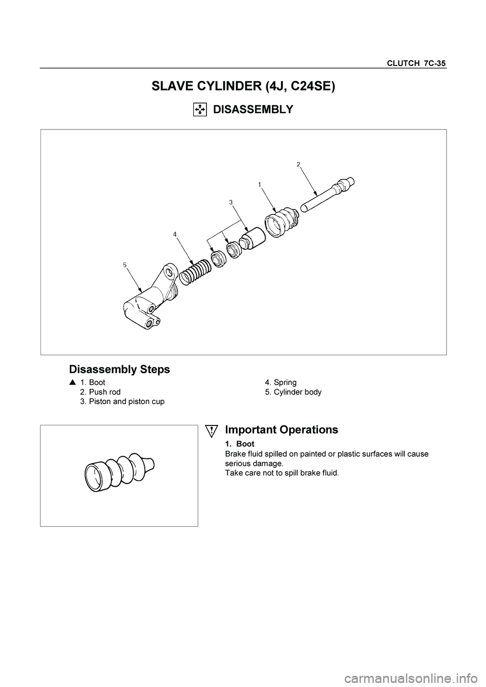
SLAVE CYLINDER (4J, C24SE)
DISASSEMBLY
Disassembly Steps
�
1. Boot
2. Push rod
3. Piston and piston cup
4. Spring
5. Cylinder body
Important Operations
1. Boot
Brake fluid spilled on painted or plastic surfaces will cause
serious damage.
Take care not to spill brake fluid.
Page 639 of 4264
CLUTCH 7C-37
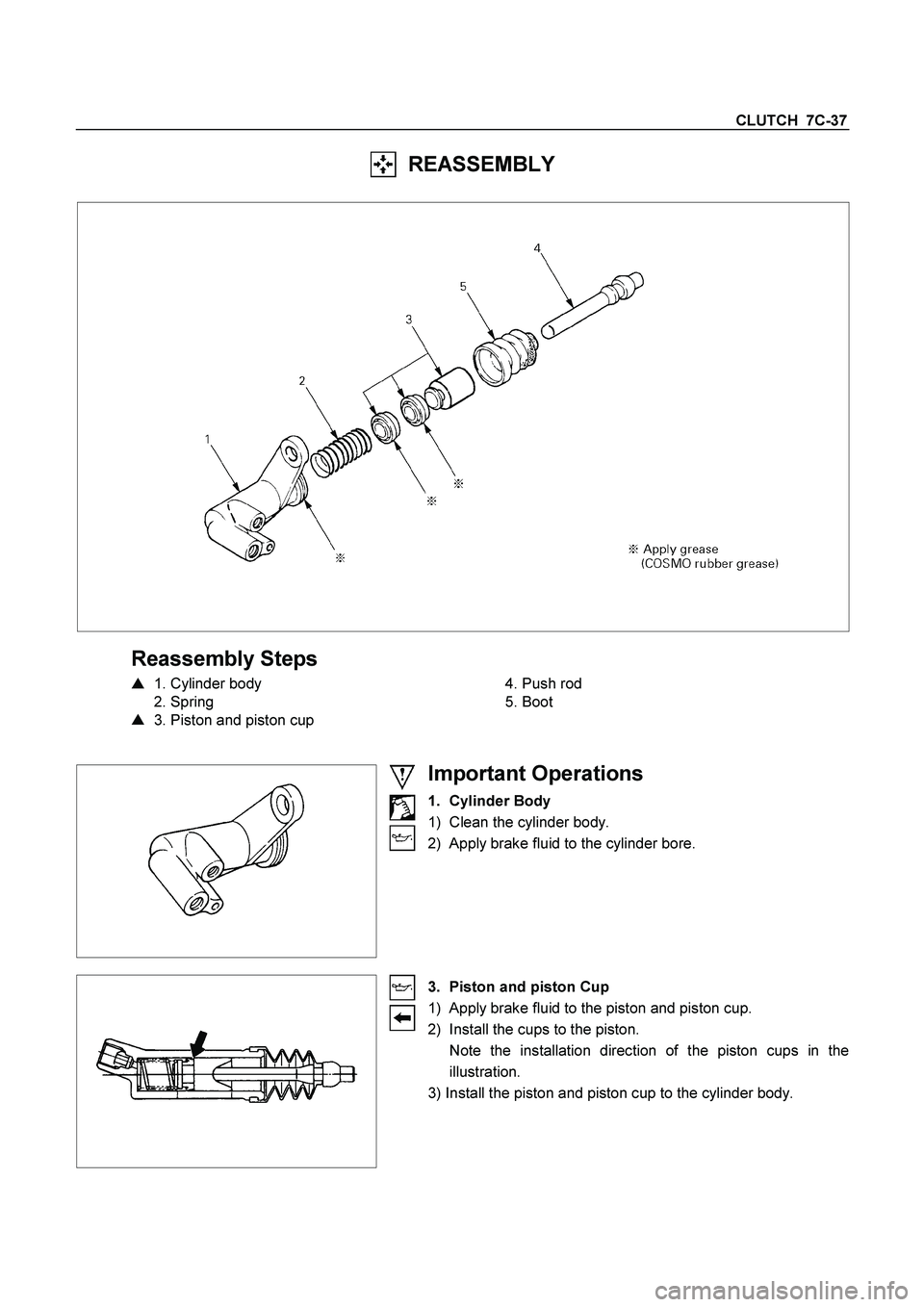
REASSEMBLY
Reassembly Steps
�
1. Cylinder body
2. Spring
�
3. Piston and piston cup
4. Push rod
5. Boot
Important Operations
1. Cylinder Body
1) Clean the cylinder body.
2) Apply brake fluid to the cylinder bore.
3. Piston and piston Cup
1) Apply brake fluid to the piston and piston cup.
2) Install the cups to the piston.
Note the installation direction of the piston cups in the
illustration.
3) Install the piston and piston cup to the cylinder body.

 fastening
the ball retainer to the center shaft.
7. Remove ball retainer, ball guide and bellows.
8. Use")
 mm(in)
Standard Limit
10.0 (0.394) 1.8 (0.071)
Replace the front disc pad whenever the pad wear indicator
makes a s")