Page 53 of 4264
SUPPLEMENTAL RESTRAINT SYSTEM 9A-33
4. Push the four pins at 5�6 mm bar.
060R300045
5. Cancel the lock four pins.
6. Disconnect the SRS air bag connector pin.
060R300042
7. Disconnect the SRS air bag connector and horn
lead connector located behind the air bag
assembly and remove the air bag assembly.
060R300041
Installation
1. Connect the SRS air bag connector and horn lead
connector.
060R300041
Page 56 of 4264
9A-36 SUPPLEMENTAL RESTRAINT SYSTEM
Installation
1. Install the steering wheel and align the setting
marks.
060R300024
NOTE: Confirm SRS and Horn harness connector is
fixed by the steering wheel.
RTW33BSH000601
2. Tighten the steering wheel fixing nut to the
specified torque.
Torque : 34 N�
�� �m (3.5 kg�
�� �m/25 lb ft)
3. Install the SRS air bag assembly. (Refer to “Drive
r
Air Bag Assembly” in this section)
Page 59 of 4264
SUPPLEMENTAL RESTRAINT SYSTEM 9A-39
NOTE: Confirm SRS and Horn harness connector is
fixed by the steering wheel.
RTW33BSH000601
9. Tighten the steering wheel fixing nut to the
specified torque.
Torque: 35 N�
�� �m (3.5 kg�
�� �m/25 lb ft)
10. Install the SRS air bag assembly. (Refer to “Drive
r
Air Bag Assembly in this section).
Page 63 of 4264
SUPPLEMENTAL RESTRAINT SYSTEM 9A-43
NOTE: Confirm SRS and Horn harness connector is
fixed by the steering wheel.
RTW33BSH000601
14.Tighten the steering wheel fixing nut to the
specified torque.
Torque: 35 N�
�� �m (3.5 kg�
�� �m/25 lb ft)
15. Install the SRS air bag assembly. (Refer to “Drive
r
Air Bag Assembly in this section)
Page 660 of 4264

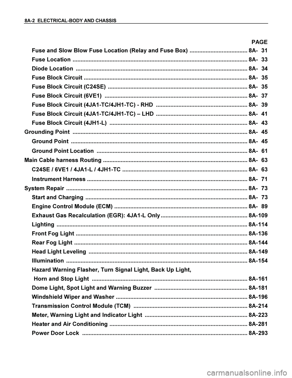
8A-2 ELECTRICAL-BODY AND CHASSIS
PAGE
Fuse and Slow Blow Fuse Location (Relay and Fuse Box) .................................... 8A- 31
Fuse Location ............................................................................................................. 8A- 33
Diode Location ........................................................................................................... 8A- 34
Fuse Block Circuit ...................................................................................................... 8A- 35
Fuse Block Circuit (C24SE) ....................................................................................... 8A- 35
Fuse Block Circuit (6VE1) ......................................................................................... 8A- 37
Fuse Block Circuit (4JA1-TC/4JH1-TC) - RHD ......................................................... 8A- 39
Fuse Block Circuit (4JA1-TC/4JH1-TC) – LHD ......................................................... 8A- 41
Fuse Block Circuit (4JH1-L) ...................................................................................... 8A- 43
Grounding Point ............................................................................................................. 8A- 45
Ground Point .............................................................................................................. 8A- 45
Ground Point Location .............................................................................................. 8A- 61
Main Cable harness Routing .......................................................................................... 8A- 63
C24SE / 6VE1 / 4JA1-L / 4JH1-TC .............................................................................. 8A- 63
Instrument Harness .................................................................................................... 8A- 71
System Repair .................................................................................................................8A- 73
Start and Charging ..................................................................................................... 8A- 73
Engine Control Module (ECM) ................................................................................... 8A- 89
Exhaust Gas Recalculation (EGR): 4JA1-L Only ...................................................... 8A- 109
Lighting ....................................................................................................................... 8A- 114
Front Fog Light ........................................................................................................... 8A- 136
Rear Fog Light ............................................................................................................ 8A- 144
Head Light Leveling ................................................................................................... 8A- 149
Illumination ................................................................................................................. 8A- 154
Hazard Warning Flasher, Turn Signal Light, Back Up Light,
Horn and Stop Light ................................................................................................. 8A- 161
Dome Light, Spot Light and Warning Buzzer .......................................................... 8A- 181
Windshield Wiper and Washer .................................................................................. 8A- 196
Transmission Control Module (TCM) ....................................................................... 8A- 214
Meter, Warning Light and Indicator Light ................................................................ 8A- 223
Heater and Air Conditioning ...................................................................................... 8A- 281
Power Door Lock ....................................................................................................... 8A- 293
Page 669 of 4264
ELECTRICAL-BODY AND CHASSIS 8A-11
SYMBOLS AND ABBREVIATIONS
SYMBOLS
Symbol Meaning of Symbol Symbol Meaning of Symbol
Fuse
Bulb
Fusible link
Double filament bulb
Fusible link wire
Motor
Switch
Variable resistor Rheostat
Switch
Coil (inductor), solenoid,
magnetic valve
Switch (Normal close type)
Contact wiring
Relay
Battery
Diode
Connector
Electronic Parts
Light emitting diode
Resistor
Reed switch
Speaker
Condenser
Buzzer
Horn
Circuit breaker
Vacuum switching valve
Page 686 of 4264
8A-28 ELECTRICAL-BODY AND CHASSIS
RELAY LOCATION (RELAY AND FUSE BOX)
RELAY & FUSE BOX
RHD
NO. RELAY (C24SE) RELAY (6VE1) RELAY
(4JA1-TC/4JH1-TC)RELAY (4JA1-L)
X-1 RELAY; TAIL LIGHT
� � �
X-2 RELAY; FUEL PUMP
� RELAY; FRT FOG RELAY; FRT FOG
LIGHT
X-3 RELAY; HORN
� � �
X-4 RELAY; DIMMER
� � �
X-5 RELAY; FOG LIGHT
� RELAY; GLOW RELAY; GLOW
X-6 RELAY; STARTER
� RELAY; COND, FAN RELAY; CSD
X-7 RELAY; COND, FAN
� RELAY; RR FOG
�
X-8
� � RELAY; STARTER RELAY; STARTER
X-9 RELAY; HAZARD-RH
� � �
X-10 RELAY; HAZARD-LH
� � �
X-11 RELAY; HEATER
� � �
X-12 RELAY; HEAD
LIGHT � � �
X-13
� RELAY; ECM MAIN
� RELAY; COND, FAN
X-14 RELAY; A/C COMP
� � �
X-15 RELAY; THERMO
� � �
Page 687 of 4264
ELECTRICAL-BODY AND CHASSIS 8A-29
RELAY LOCATION (RELAY AND FUSE BOX)
RELAY & FUSE BOX
LHD
NO. RELAY (C24SE) RELAY (6VE1) RELAY
(4JA1-TC 4JH1-TC)RELAY (4JA1-L)
X-1 RELAY; TAIL LIGHT
� � �
X-2 RELAY; FUEL PUMP
� RELAY; FRT FOG RELAY; FRT FOG
LIGHT
X-3 RELAY; HORN
� � �
X-4 RELAY; DIMMER
� � �
X-5 RELAY; FRT FOG
LIGHT RELAY; FOG LIGHT RELAY; GLOW RELAY; GLOW
X-6 RELAY; STARTER
� RELAY; COND, FAN RELAY; CSD
X-7 RELAY; COND, FAN
� RELAY; RR FOG
�
X-8
� � RELAY; STARTER
�
X-9
� � SHORT
CONNECTOR
(with cooler) �
X-10
� � � �
X-11 RELAY; HEATER
� � �
X-12 RELAY; HEAD
LIGHT � � �
X-13
� RELAY; ECM MAIN
� RELAY; COND, FAN
X-14 RELAY; A/C COMP
� � �
X-15 RELAY; THERMO
� � �