Page 3183 of 4264

MANUAL TRANSMISSION 7B1-19
Disassembly
1. Clean the exterior of the unit with solvent.
2. Remove the drain plug from the transmission case
and drain the lubricant.
3. Remove the clutch release bearing with spring
(6)(11) from the transmission case.
4. Remove the shift fork (7)(12), and boot. (Diesel
engine, C24NE)
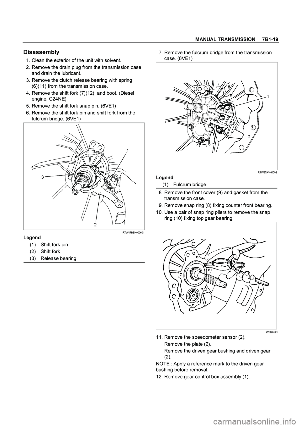
5. Remove the shift fork snap pin. (6VE1)
6. Remove the shift fork pin and shift fork from the
fulcrum bridge. (6VE1)
RTW47BSH000601
Legend
(1) Shift fork pin
(2) Shift fork
(3) Release bearing
7. Remove the fulcrum bridge from the transmission
case. (6VE1)
RTW37ASH0002
Legend
(1) Fulcrum bridge
8. Remove the front cover (9) and gasket from the
transmission case.
9. Remove snap ring (8) fixing counter front bearing.
10. Use a pair of snap ring pliers to remove the snap
ring (10) fixing top gear bearing.
226RS001
11. Remove the speedometer sensor (2).
Remove the plate (2).
Remove the driven gear bushing and driven gear
(2).
NOTE : Apply a reference mark to the driven gear
bushing before removal.
12. Remove gear control box assembly (1).
Page 3241 of 4264

MANUAL TRANSMISSION 7B1-77
Disassembly
1. Clean the exterior of the unit with solvent.
2. Remove the drain plug from the transmission case
and drain the lubricant.
3. Remove the clutch release bearing with spring (5)
from the transmission case.
4. Remove the shift fork, and boot. (Diesel engine,
C24NE)
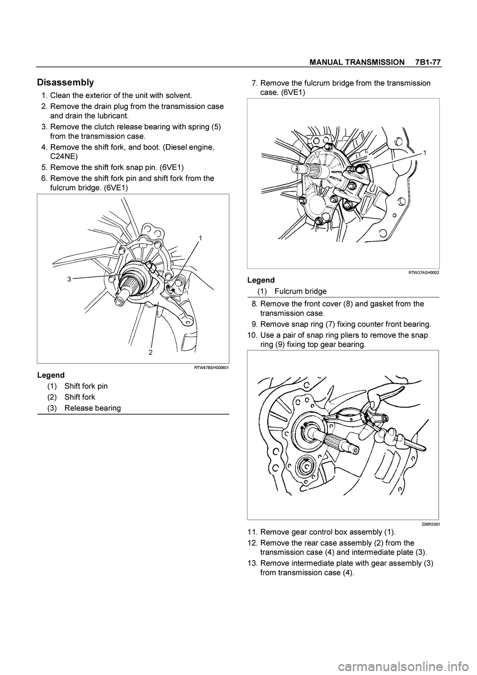
5. Remove the shift fork snap pin. (6VE1)
6. Remove the shift fork pin and shift fork from the
fulcrum bridge. (6VE1)
RTW47BSH000601
Legend
(1) Shift fork pin
(2) Shift fork
(3) Release bearing
7. Remove the fulcrum bridge from the transmission
case. (6VE1)
RTW37ASH0002
Legend
(1) Fulcrum bridge
8. Remove the front cover (8) and gasket from the
transmission case.
9. Remove snap ring (7) fixing counter front bearing.
10. Use a pair of snap ring pliers to remove the snap
ring (9) fixing top gear bearing.
226RS001
11. Remove gear control box assembly (1).
12. Remove the rear case assembly (2) from the
transmission case (4) and intermediate plate (3).
13. Remove intermediate plate with gear assembly (3)
from transmission case (4).
Page 3443 of 4264
POWER-ASSISTED STEERING SYSTEM 3B-13
Power Steering Unit Disassembled View
This illustration is based on the RHD model. 440R300003
Legend
(1) Tie-rod End
(2) Lock Nut
(3) Clip
(4) Bellows
(5) Band
(6) Tie-rod Assembly
(7) Oil Line
(8) Inner Ball Joint Assembly
(9) Tab Washer
(10) Mounting Rubber
(11) Housing Assembly
Disassembly
NOTE: The valve housing is made of aluminum and
care should be exercised when clamping in a vise, etc.
to prevent distortion or damage.
1. Loosen lock nut and remove tie-rod end.
2. Remove clip and band, then remove bellows.
3. Remove tie-rod assembly.
To remove, move the boot toward the tie-rod end,
then remove tab washer.
4. Remove oil line, mounting rubber and dust cover.
Inspection and Repair
Inspect the following parts for wear, damage or any
abnormal conditions.
Page 3501 of 4264
FRONT SUSPENSION 3C-9
Shock Absorber
Shock Absorber and Associated Parts
RTW440LF001201
Legend
(1)
Shock Absorber ASM with coil
(2)
Nut
(3)
Nut
(4)
Nut
(5)
Lower ball joint Nut and cot ter pin
(6)
Nut
(7)
Bolt
(8)
Cam bolt
Removal
1. Raise the vehicle and support it with suitable
safety stands.
2. Remove wheel and tire assembly. Refer to Wheel
Replacement in this section.
3. Remove nut (6).
CAUTION: Be careful not o break the ball joint boot.
Page 3507 of 4264
FRONT SUSPENSION 3C-15
Stabilizer Bar
Stabilizer Bar and Associated Parts
RTW340LF000901
Legend
(1)
Stabilizer Bar
(2)
Link
(3)
Nut
(4)
Nut
(5)
Bracket and Bolt
(6)
Rubber Bushing
Removal
1. Raise the vehicle and support the frame with
suitable safety stands.
2. Remove wheel and tire assembly. Refer to Wheel
Replacement in this section.
3. Remove nut (3) and (4).
CAUTION: Be careful not to break the ball joint
boot.
4. Remove link.
5. Remove bracket and bolt.
6. Remove stabilizer bar.
7. Remove rubber bushing.
Page 3510 of 4264

3C-18 FRONT SUSPENSION
6. Remove the stabilizer link nut. Right and left.
7. Remove the wheel speed sensor from the knuckle.
8. Remove back plate.
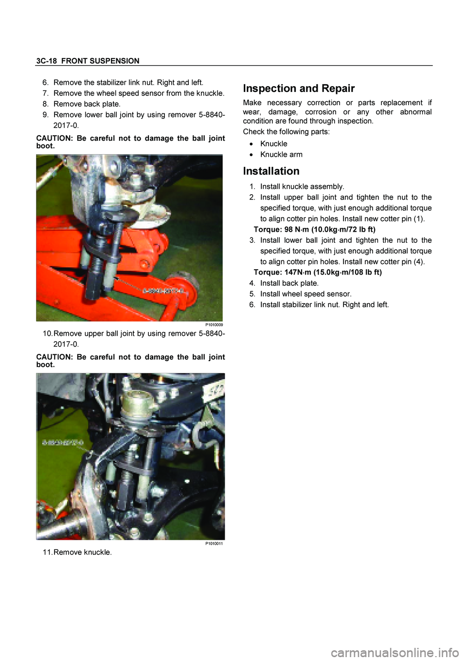
9. Remove lower ball joint by using remover 5-8840- 2017-0.
CAUTION: Be careful not to damage the ball joint
boot.
P1010009
10. Remove upper ball joint by using remover 5-8840-
2017-0.
CAUTION: Be careful not to damage the ball joint
boot.
P1010011
11. Remove knuckle.
Inspection and Repair
Make necessary correction or parts replacement if
wear, damage, corrosion or any other abnormal
condition are found through inspection.
Check the following parts:
�
Knuckle
�
Knuckle arm
Installation
1. Install knuckle assembly.
2. Install upper ball joint and tighten the nut to the
specified torque, with just enough additional torque
to align cotter pin holes. Install new cotter pin (1).
Torque: 98 N �
��
�
m (10.0kg �
��
�
m/72 lb ft)
3. Install lower ball joint and tighten the nut to the specified torque, with just enough additional torque
to align cotter pin holes. Install new cotter pin (4).
Torque: 147N �
��
�
m (15.0kg �
��
�
m/108 lb ft)
4. Install back plate.
5. Install wheel speed sensor.
6. Install stabilizer link nut. Right and left.
Page 3512 of 4264

3C-20 FRONT SUSPENSION
5. Remove nut (8).
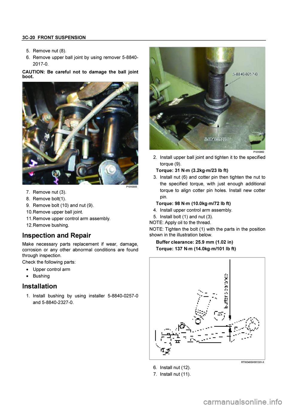
6. Remove upper ball joint by using remover 5-8840-
2017-0.
CAUTION: Be careful not to damage the ball joint
boot.
P1010005
7. Remove nut (3).
8. Remove bolt(1).
9. Remove bolt (10) and nut (9).
10. Remove upper ball joint.
11. Remove upper control arm assembly.
12. Remove bushing.
Inspection and Repair
Make necessary parts replacement if wear, damage,
corrosion or any other abnormal conditions are found
through inspection.
Check the following parts:
�
Upper control arm
�
Bushing
Installation
1. Install bushing by using installer 5-8840-0257-0
and 5-8840-2327-0.
P1010062
2. Install upper ball joint and tighten it to the specified
torque (9).
Torque: 31 N �
��
�
m (3.2kg �
��
�
m/23 lb ft)
3. Install nut (6) and cotter pin then tighten the nut to the specified torque, with just enough additional
torque to align cotter pin holes. Install new cotte
r
pin.
Torque: 98 N �
��
�
m (10.0kg
�
��
�
m/72 lb ft)
4. Install upper control arm assembly.
5. Install bolt (1) and nut (3).
NOTE: Apply oil to the thread.
NOTE: Tighten the bolt (1) with the parts in the position
shown in the illustration below.
Buffer clearance: 25.9 mm (1.02 in)
Torque: 137 N �
��
�
m (14.0kg �
��
�
m/101 lb ft)
RTW340SH001301-X
6. Install nut (12).
7. Install nut (11).
Page 3516 of 4264
3C-24 FRONT SUSPENSION
Upper Ball Joint
Upper Ball Joint and Associated Parts
RTW340LF001101
Legend
(1)
Bolt
(2)
Upper Ball Joint
(3)
Nut
(4)
Nut and Cotter Pin
(5)
Nut
Removal
1. Raise the vehicle and support the frame with
suitable safety stands.
2. Remove wheel and tire assembly. Refer to wheel
in this section.
3. Remove nut (5).
4. Remove upper ball joint nut and cotter pin, then
use remover 5-8840-2017-0 to remove the uppe
r
ball joint from the knuckle.
CAUTION: Be careful not to damage the ball joint
boot and brake hose.