Page 215 of 4264
REAR AXLE 4B-51
2) Axle Case Leakage
Checkpoint Trouble Cause Countermeasure
Tighten the drain plug and/or
replace the gasket(s)Loose drain plug and/or
defective gasket(s) NG
Reapply the liquid gasket
Tighten the bolts to the
specified torque
Clean the air breather
Liquid gasket seal bad
Loose bolts
Air breatherClogged air breather
Differential carrier
Replace the axle caseAxle caseCracked axle case
NG NG NG NG
OK OK
OK
Oil filler and drain plug
Page 261 of 4264
FRONT WHEEL DRIVE 4C1-41
20. Differential Assembly
(1) Clean the faces of the front axle case and differential
carrier.
Apply the recommended liquid gasket or its equivalent to
the sealing side of the axle case and the carrier.
(2) Attach the differential case and the carrier assembly to the
front axle case and tighten the nuts and bolts. The axle
case bolt is used for drainage.
Torque N�
m (kgf�
m/lb�
ft)
26 �
5 (2.6 �
0.5/18.8 �
3.6)
(3) Install the axle shaft assemblies as instructed earlier in this
section under “Axle Shaft Replacement”.
(4) Fill the axle case with hypoid gear lubricant, to just belo
w
the filler hole.
Lubricant capacity liter (US/UK gal)
1.4 (0.37/0.31)
Page 303 of 4264
SHIFT ON THE FLY SYSTEM 4C2-5
DISASSEMBLY
1. Filler Plug
Remove filler plug and packing and drain oil.
2. Bolt
Loosen mounting bracket fitting bolts and remove front axle
drive shaft from front axle case.
3. Front Axle Drive Shaft (LH side)
4. Bolt
Loosen actuator ASM fitting bolts.
5. Actuator Assembly
Draw out actuator ASM.
6. Bolt
Remove hosing fitting bolts.
7. Housing
8. Sleeve
9. Clutch Gear
412RW017
10. Snap Ring
Remove snap ring from front axle case by using a snap ring
pliers.
11.Inner Shaft
Take out inner shaft from front axle case.
412RW016
12.Snap Ring
Remove snap ring from inner shaft by using a snap ring
pliers.
412RW015
13.Inner Shaft Bearing
Remove inner shaft bearing by using a special tool and
press.
Remove : 5-8840-2197-0 (J-37452)
NOTE:
Be careful not to damage the shaft.
Page 1134 of 4264

6 – 14 TROUBLESHOOTING
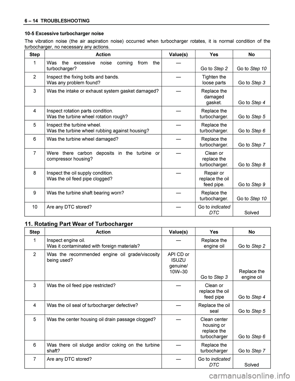
10-5 Excessive turbocharger noise
The vibration noise (the air aspiration noise) occurred when turbocharger rotates, it is normal condition of the
turbocharger, no necessary any actions.
Step Action Value(s) Yes No
1 Was the excessive noise coming from the
turbocharger? —
Go to Step 2 Go to Step 10
2 Inspect the fixing bolts and bands.
Was any problem found? — Tighten the
loose parts Go to Step 3
3 Was the intake or exhaust system gasket damaged?— Replace the
damaged
gasket. Go to Step 4
4 Inspect rotation parts condition.
Was the turbine wheel rotation rough? — Replace the
turbocharger. Go to Step 5
5 Inspect the turbine wheel.
Was the turbine wheel rubbing against housing? — Replace the
turbocharger. Go to Step 6
6 Was the turbine wheel damaged? — Replace the
turbocharger. Go to Step 7
7 Were there carbon deposits in the turbine or
compressor housing? — Clean or
replace the
turbocharger. Go to Step 8
8 Inspect the oil supply condition.
Was the oil feed pipe clogged? — Repair or
replace the oil
feed pipe. Go to Step 9
9 Was the turbine shaft bearing worn? — Replace the
turbocharger. Go to Step 10
10 Are any DTC stored? — Go to indicated
DTC Solved
11. Rotating Part Wear of Turbocharger
Step Action Value(s) Yes No
1 Inspect engine oil.
Was it contaminated with foreign materials? — Replace the
engine oil Go to Step 2
2 Was the recommended engine oil grade/viscosity
being used? API CD or
ISUZU
genuine/
10W–30
Go to Step 3 Replace the
engine oil
3 Was the oil feed pipe restricted? — Clean or
replace the oil
feed pipe Go to Step 4
4 Was the oil seal of turbocharger defective? — Replace the oil
seal Go to Step 5
5 Was the center housing oil drain passage clogged? — Clean center
housing or
replace the
turbocharger Go to Step 6
6 Was there oil sludge and/or coking on the turbine
shaft? — Replace the
turbocharger Go to Step 7
7 Are any DTC stored? — Go to indicated
DTC Solved
Page 1179 of 4264

ENGINE MECHANICAL 6A – 39
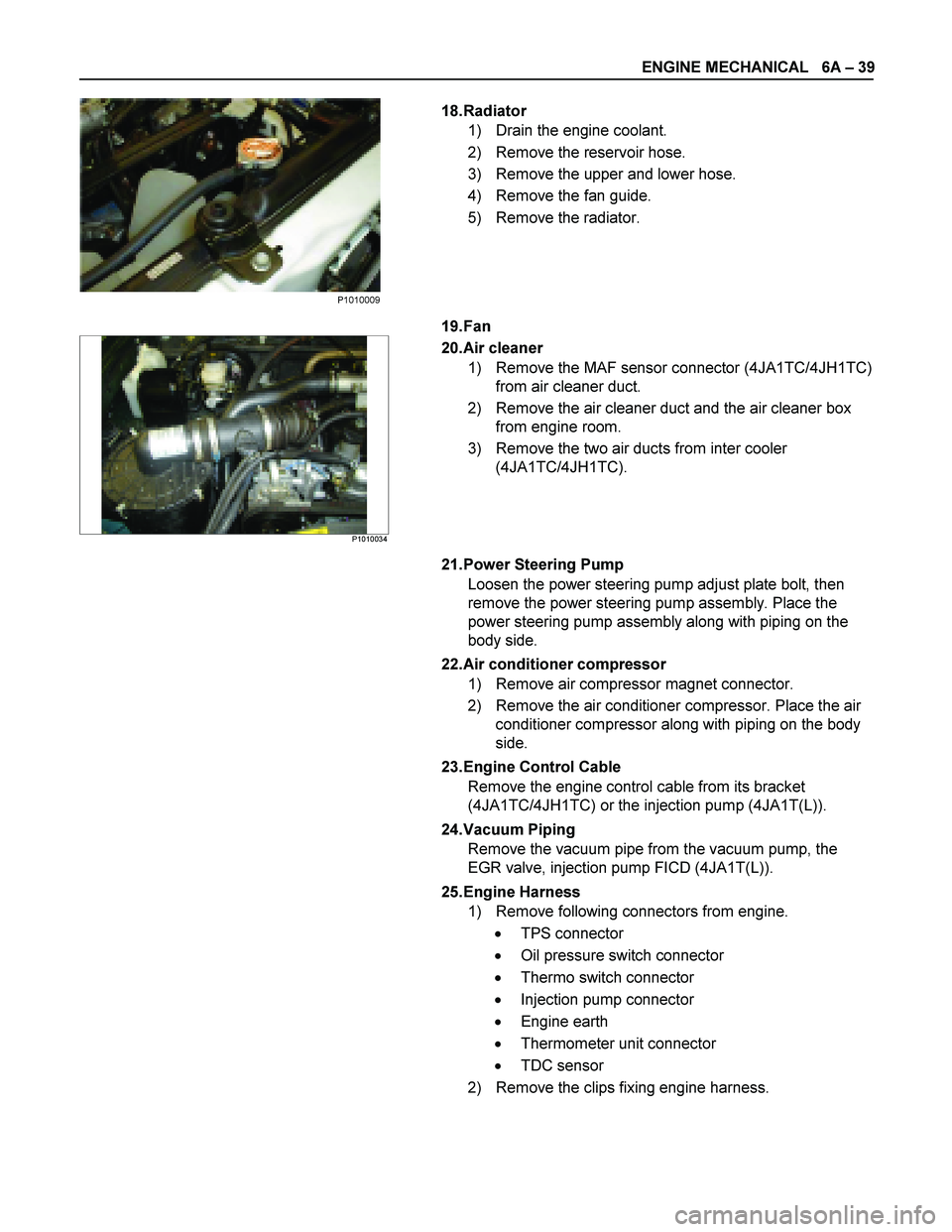
18. Radiator
1) Drain the engine coolant.
2) Remove the reservoir hose.
3) Remove the upper and lower hose.
4) Remove the fan guide.
5) Remove the radiator.
19. Fan
P1010034
20. Air cleaner
1) Remove the MAF sensor connector (4JA1TC/4JH1TC) from air cleaner duct.
2) Remove the air cleaner duct and the air cleaner box from engine room.
3) Remove the two air ducts from inter cooler (4JA1TC/4JH1TC).
21. Power Steering Pump Loosen the power steering pump adjust plate bolt, then
remove the power steering pump assembly. Place the
power steering pump assembly along with piping on the
body side.
22. Air conditioner compressor 1) Remove air compressor magnet connector.
2) Remove the air conditioner compressor. Place the air conditioner compressor along with piping on the body
side.
23. Engine Control Cable Remove the engine control cable from its bracket
(4JA1TC/4JH1TC) or the injection pump (4JA1T(L)).
24. Vacuum Piping Remove the vacuum pipe from the vacuum pump, the
EGR valve, injection pump FICD (4JA1T(L)).
25. Engine Harness 1) Remove following connectors from engine.
� TPS connector
� Oil pressure switch connector
� Thermo switch connector
� Injection pump connector
� Engine earth
� Thermometer unit connector
� TDC sensor
2) Remove the clips fixing engine harness.
P1010009
Page 1182 of 4264
6A – 42 ENGINE MECHANICAL
ENGINE REPAIR KIT
RTW36ALF000601
Removal Steps
1. Cylinder head gasket
2. Head cover gasket
3. Head cover cap nut gasket
4. Drain cock gasket
5. Crankshaft rear oil seal
6. Gear case gasket
7. Oil pan drain plug gasket
8. Oil pan gasket
9. Oil filter gasket
10. Joint bolt gasket 11. Vacuum pump gasket
12. Water pump O-ring
13. Water outlet pipe gasket
14. Intake pipe gasket
15. Thermostat housing gasket
16. Intake manifold gasket
17. Exhaust manifold gasket
18. Nozzle holder O-ring
19. Nozzle holder gasket
20. Crankshaft front oil seal
NOTE
Discard all O-rings, gaskets, and seals removed at disassembly and replace them with new ones. Reuse of
these parts will result in oil, water, and gas leakage.
Page 1290 of 4264

6B – 10 ENGINE COOLING
WATER PUMP
REMOVAL AND INSTALLATION
Read this Section carefully before performing any removal and installation procedure. This Section gives you
important points as well as the order of operation. Be sure that you understand everything in this Section before you
begin.
Removal
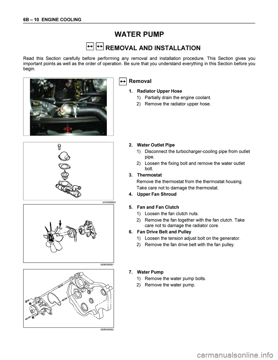
1. Radiator Upper Hose
1) Partially drain the engine coolant.
2) Remove the radiator upper hose.
031R300003
2. Water Outlet Pipe
1) Disconnect the turbocharger-cooling pipe from outlet pipe.
2) Loosen the fixing bolt and remove the water outlet bolt.
3. Thermostat
Remove the thermostat from the thermostat housing.
Take care not to damage the thermostat.
4. Upper Fan Shroud
5. Fan and Fan Clutch 1) Loosen the fan clutch nuts.
2) Remove the fan together with the fan clutch. Take care not to damage the radiator core.
6. Fan Drive Belt and Pulley
1) Loosen the tension adjust bolt on the generator.
2) Remove the fan drive belt with the fan pulley.
030R300001 7. Water Pump
1) Remove the water pump bolts.
2) Remove the water pump.
030R300002
Page 1293 of 4264

ENGINE COOLING 6B – 13
THERMOSTAT
REMOVAL AND INSTALLATION
Read this Section carefully before performing any removal and installation procedure. This Section gives you
important points as well as the order of operation. Be sure that you understand everything in this Section before you
begin.
Removal
1. Radiator Upper Hose
1) Partially drain the engine coolant.
2) Remove the radiator upper hose.
2. Water Outlet Pipe 3) Disconnect the turbocharger-cooling pipe from outlet pipe.
4) Loosen the fixing bolt and remove the water outlet bolt.
3. Thermostat
Remove the thermostat from the thermostat housing.
Take care not to damage the thermostat.
031R300003
Inspection and Repair
Make the necessary adjustments, repairs, and part
replacements if excessive wear or damage is discovered
during inspection.
031RY00005
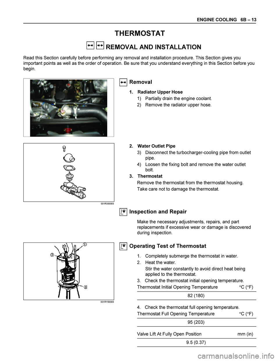
Operating Test of Thermostat
1. Completely submerge the thermostat in water.
2. Heat the water. Stir the water constantly to avoid direct heat being
applied to the thermostat.
3. Check the thermostat initial opening temperature.
Thermostat Initial Opening Temperature �C ( �F)
82 (180)
4. Check the thermostat full opening temperature.
Thermostat Full Opening Temperature �C ( �F)
95 (203)
Valve Lift At Fully Open Position mm (in)
9.5 (0.37)