Page 1930 of 4264

Draining and Refilling Cooling
System
Before draining the cooling system, inspect the system
and perform any necessary service to ensure that it is
clean, does n")
6B-6 ENGINE COOLING (6VE1 3.5L)
Draining and Refilling Cooling
System
Before draining the cooling system, inspect the system
and perform any necessary service to ensure that it is
clean, does not leak and is in proper working order.
The engine coolant (EC) level should be between the
“ MIN" and “MAX" lines of reserve tank when the engine
is cold. If low, check for leakage and add EC up to the
“ MAX" line.
There should not be any excessive deposit of rust o
r
scales around the radiator cap or radiator filler hole, and
the EC should also be free from oil.
Replace the EC if excessively dirty.
1. Completely drain the cooling system by opening the
drain plug at the bottom of the radiator.
P1010064
2. Remove the radiator cap.
WARNING: To avoid the danger of being burned, do
not remove the cap while the engine and radiato
r
are still hot. Scalding fluid and steam can be blown
out under pressure.
3. Disconnect all hoses from the EC reserve tank.
Scrub and clean the inside of the reserve tank with
soap and water. Flush it well with clean water, then
drain it. Install the reserve tank and hoses.
4. Refill the cooling system with the EC using a
solution that is 50 percent antifreeze.
Procedure for filling with coolant (in case of full change)
Make sure that the engine is cool.
Open radiator cap pour coolant up to filler neck.
Pour coolant into reservoir tank up to “MAX" line.
Tighten radiator cap and start the engine. Afte
r
idling for 2 to 3 minutes, stop the engine and reopen
radiator cap. If the water level is lower, replenish.
WARNING: When the coolant is heated to a high
temperature, be sure not to loosen or remove the
radiator cap. Otherwise you might get scalded by
not vapor or boiling water. To open the radiato
r
cap, put a piece of thick cloth on the cap and
loosen the cap slowly to reduce the pressure when
the coolant has become cooler.
After tightening radiator cap, warm up the engine at
about 2000 rpm. Set heater adjustment to the
highest temperature position, and let the coolan
t
circulate also into heater water system.
Check to see the thermostat has opened through
the needle position of water thermometer, conduct a
5 –minute idling again and stop the engine.
When the engine has been cooled, check filler neck
for water level and replenish if required. Should
extreme shortage of coolant is found, check the
cooling system and reservoir tank hose for leakage.
Pour coolant into the reservoir tank up to “MAX"
line.
Page 1938 of 4264

6. After directly filling the radiator, fill the reservoir to
the maximum level.
7. Install and tighten radiator cap and start the engine.
After idling for 2 to 3")
6B-14 ENGINE COOLING (6VE1 3.5L)
6. After directly filling the radiator, fill the reservoir to
the maximum level.
7. Install and tighten radiator cap and start the engine.
After idling for 2 to 3 minutes, stop the engine and
reopen radiator cap. If the water level is lower,
replenish.
WARNING: When the coolant is heated to a high
temperature, be sure not to loosen or remove the
radiator cap. Otherwise you might get scalded by
hot vapor or boiling water. To open the radiato
r
cap, put a piece of thick cloth on the cap and
loosen the cap slowly to reduce the pressure when
the coolant has become cooler.
8.
After tightening radiator cap, warm up the engine at
about 2,000 rpm.
Set heater adjustment to the highest temperature
position, and let the coolant circulate also into
heater water system.
9. Check to see the thermostat has opened through
the needle position of water thermometer, conduct a
5-minute idling again and stop the engine.
10. When the engine has been cooled, check filler neck
for water level and replenish if required. Should
extreme shortage of coolant is found, check the
coolant system and reservoir tank hose for leakage.
11. Fill the coolant into the reservoir tank up to “MAX"
line.
Page 2027 of 4264
3.5L ENGINE DRIVEABILITY AND EMISSIONS 6E-31
RELAY AND FUSE BOX LOCATION (LHD & RHD)
RELAY & FUSE BOX
RELAY
NO. Relay name
X-1 RELAY; TAIL LIGHT
X-2 RELAY; FUEL PUMP
X-3 RELAY; HORN
X-4 RELAY; DIMMER
X-5 RELAY; FOG LIGHT
X-6 RELAY; STARTER
X-7 RELAY; COND, FAN
X-8 RELAY; �
X-9 RELAY; HAZARD-RH
X-10 RELAY; HAZARD-LH
X-11 RELAY; HEATER
X-12 RELAY; HEAD LIGHT
X-13 RELAY; ECM MAIN
X-14 RELAY; A/C COMP
X-15 RELAY; THERMO
FUSE
�������� �
���
���
����� ���������
����� �������������
����� ���������
����� �������������
����� ������ ����
���!� �������� �
��������� �
�����
����������"���������� �
����������
��������� �
�����
����������#���������� �
����������
���$� ���������������
������ �������� �%��%�
��������
��������
������ ������&��
������ ������'(�
������ �����)����
����!� �����)�*��(�
SLOW BLOW FUSE
�������� �+,-��+,-��
���
���
������ �����������
��������
��������
������ ���������(.�����
������ �����������
����!� �����������
����"� �����������
����#� ������ �'���
����$� ����������
Page 2051 of 4264

The VSS is a magnet rotated by the transmission output
shaft. The VSS uses a hall element. It interacts with the
magne")
3.5L ENGINE DRIVEABILITY AND EMISSIONS 6E-55
Vehicle Speed Sensor (VSS)
The VSS is a magnet rotated by the transmission output
shaft. The VSS uses a hall element. It interacts with the
magnetic field treated by the rotating magnet. It outputs
pulse signal. The 12 volts operating supply from the
meter fuse.
Heated Oxygen (O2) Sensor
1
(1) Bank 1 Heated Oxygen Sensor (RH)
1
(1) Bank 2 Heated Oxygen Sensor (LH)
Each oxygen sensor consists of a 4-wire low
temperature activated zirconia oxygen analyzer elemen
t
with heater for operating temperature of 315�C, and
there is one mounted on each exhaust pipe.
A constant 450millivolt is supplied by the ECM between
the two supply terminals, and oxygen concentration in
the exhaust gas is reported to the ECM as returned
signal voltage.
The oxygen present in the exhaust gas reacts with the
sensor to produce a voltage output. This voltage should
constantly fluctuate from approximately 100mV to
1000mV and the ECM calculates the pulse width
commanded for the injectors to produce the prope
r
combustion chamber mixture.
Low oxygen sensor output voltage is a lean mixture
which will result in a rich commanded to compensate.
High oxygen sensor output voltage is a rich mixture
which result in a lean commanded to compensate.
When the engine is first started the system is in "Open
Loop" operation. In "Open Loop", the ECM ignores the
signal from the oxygen sensors. When various
conditions (ECT, time from start, engine speed &
oxygen sensor output) are met, the system enters
"Closed Loop" operation. In "Closed Loop", the ECM
calculates the air fuel ratio based on the signal from the
oxygen sensors.
Heated oxygen sensors are used to minimize the
amount of time required for closed loop fuel control to
begin operation and allow accurate catalyst monitoring.
The oxygen sensor heater greatly decreases the
amount of time required for fuel control sensors to
become active.
Oxygen sensor heaters are required by catalyst monito
r
and sensors to maintain a sufficiently high temperature
which allows accurate exhaust oxygen content readings
further away from the engine.
Page 2192 of 4264
6E-196 3.5L ENGINE DRIVEABILITY AND EMISSIONS
Step Action Value (s) Yes No
5
Using the DVM and check the O2 sensor circuit for the
affected bank.
1. Ignition "On", engine "Off".
2. Disconnect the O2 sensor connector for the
affected bank.
3. Check the circuit for open, short to heater ground or
ground circuit.
Was the DVM indicated specified value?
E-77/E-78 BANK1/BANK2
V
�
�
Approximatly
450mV
Go to Step 7
Go to Step 6
6
Using the DVM and check the O2 sensor circuit for the
affected bank.
Breaker box is available:
1. Ignition "Off", engine "Off".
2. Install the breaker box as type A (ECM
disconnected).
Refer to 6E-95 page.
3. Disconnect the O2 sensor for the affected bank.
4. Check the circuit for open, short to heater ground or
short to ground circuit.
Was the problem found?
B21B22
�
Breaker BoxE-77
�
�
��
�
�
� BANK1
B21B22 Breaker Box
E-77
�
�
�
�
Page 2193 of 4264
3.5L ENGINE DRIVEABILITY AND EMISSIONS 6E-197
Step Action Value (s) Yes No
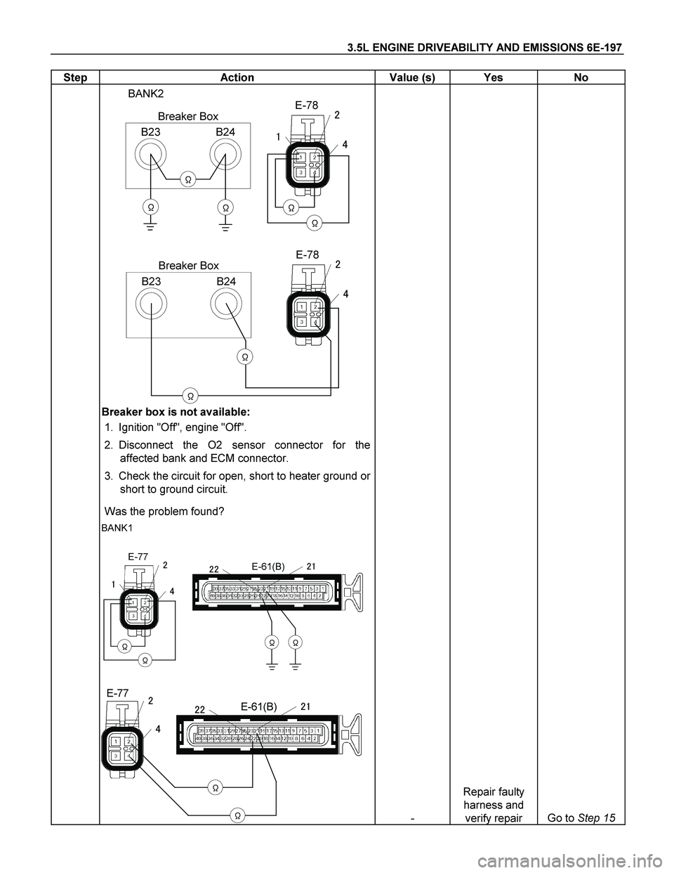
B23B24
�
Breaker BoxE-78
�
�
��
�
�
� BANK2
B23B24 Breaker Box
E-78
�
�
�
�
Breaker box is not available:
1. Ignition "Off", engine "Off".
2. Disconnect the O2 sensor connector for the
affected bank and ECM connector.
3. Check the circuit for open, short to heater ground or
short to ground circuit.
Was the problem found?
E-61(B)
��
���� BANK1
E-77
�
�
�
�
�
E-61(B)
�
�
����
E-77�
�
- Repair faulty
harness and
verify repair Go to Step 15
Page 2194 of 4264
6E-198 3.5L ENGINE DRIVEABILITY AND EMISSIONS
Step Action Value (s) Yes No
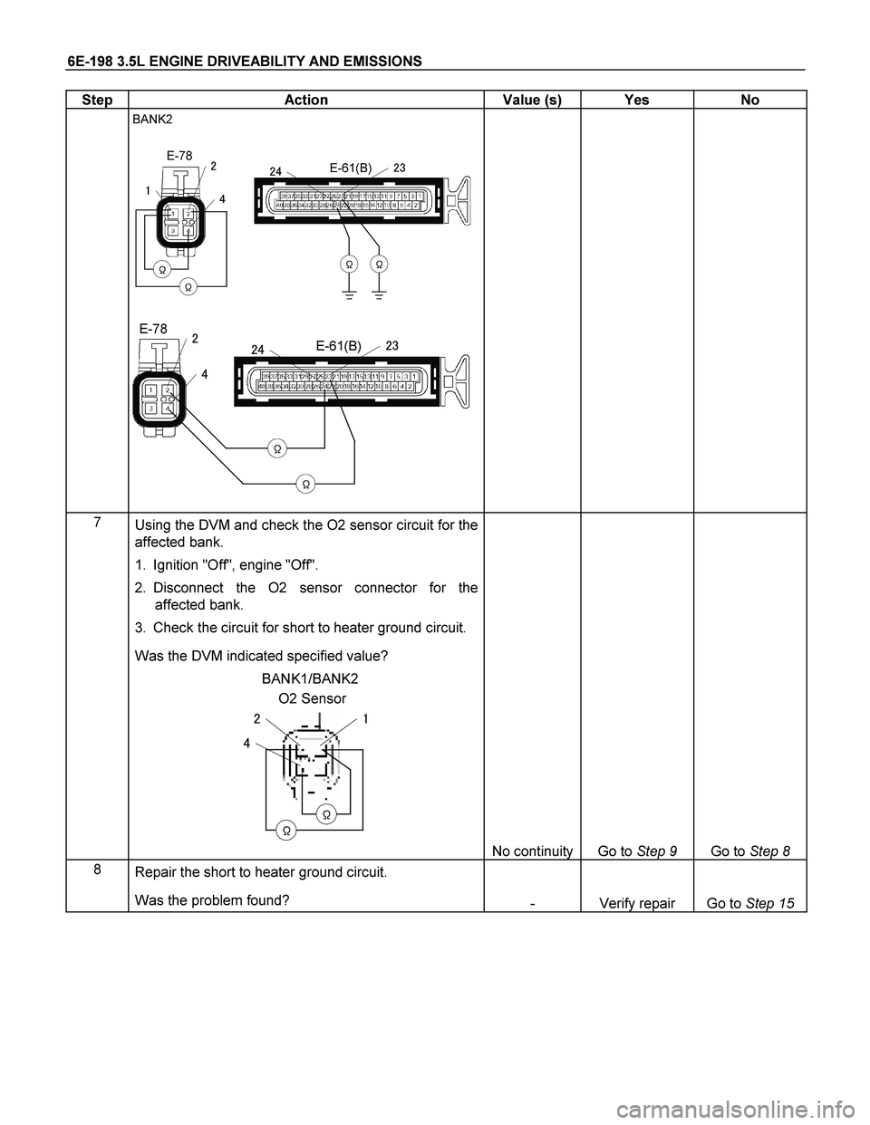
E-61(B)
��
���� BANK2
E-78
�
�
�
�
�
E-61(B)
�
�
����
E-78�
�
7
Using the DVM and check the O2 sensor circuit for the
affected bank.
1. Ignition "Off", engine "Off".
2. Disconnect the O2 sensor connector for the
affected bank.
3. Check the circuit for short to heater ground circuit.
Was the DVM indicated specified value?
O2 Sensor BANK1/BANK2
�
�
��
�
No continuity
Go to Step 9
Go to Step 8
8
Repair the short to heater ground circuit.
Was the problem found?
- Verify repair Go to Step 15
Page 2200 of 4264
6E-204 3.5L ENGINE DRIVEABILITY AND EMISSIONS
Step Action Value (s) Yes No
5
Using the DVM and check the O2 sensor circuit for the
affected bank.
1. Ignition "On", engine "Off".
2. Disconnect the O2 sensor connector for the
affected bank.
3. Check the circuit for open, short to heater ground or
ground circuit.
Was the DVM indicated specified value?
E-77/E-78 BANK1/BANK2
V
�
�
Approximatly
450mV
Go to Step 7
Go to Step 6
6
Using the DVM and check the O2 sensor circuit for the
affected bank.
1. Ignition "On", engine "Off".
2. Disconnect the O2 sensor connector for the
affected cylinder.
3. Check the circuit for short to power supply circuit.
Was the DVM indicated specifed value?
E-77/E-78 BANK1/BANK2
VV
�
�
Less than 1V
Go to Step 15
Repair faulty
harness and
verify repair

RELAY & FUSE BOX
RELAY
NO. Relay name
X-1 RELAY; TAIL LIGHT
X-2 RELAY; FUEL PUMP
X-3 RELAY; HORN
X-4")
 Yes No
5
Using the DVM and check the O2 sensor circuit for the
affected bank.
1. Ignition \"On\", engine \"Off\".
2. Discon")
 Yes No
5
Using the DVM and check the O2 sensor circuit for the
affected bank.
1. Ignition \"On\", engine \"Off\".
2. Disco")