2004 ISUZU TF SERIES dead battery
[x] Cancel search: dead batteryPage 1962 of 4264

6D1-4 ENGINE ELECTRICAL (6VE1 3.5L)
Jump Starting Procedure
1. Set the vehicle parking brake.
If the vehicle is equipped with an automatic
transmission, place the selector level in the “PARK"
position.
If the vehicle is equipped with a manual
transmission, place the shift lever in the
“ NEUTRAL" position.
Turn “OFF" the ignition.
Turn “OFF" all lights and any other accessory
requiring electrical power.
2. Look at the built –in hydrometer.
If the indication area of the built –in hydrometer is
completely clear, do not try to jump start.
3.
Attach the end of one jumper cable to the positive
terminal of the booster battery.
Attach the other end of the same cable to the
positive terminal of the discharged battery.
Do not allow the vehicles to touch each other. This
will cause a ground connection, effectively
neutralizing the charging procedure.
Be sure that the booster battery has a 12 volt rating.
4. Attach one end of the remaining cable to the
negative terminal of the booster battery.
Attach the other end of the same cable to a solid
engine ground (such as the air conditioning
compressor bracket or the generator mounting
bracket) of the vehicle with the discharged battery.
The ground connection must be at least 450 mm
(18 in.) from the battery of the vehicle whose battery
is being charged.
WARNING: NEVER ATTACH THE END OF THE
JUMPER CABLE DIRECTLY TO THE NEGATIVE
TERMINAL OF THE DEAD BATTERY.
5. Start the engine of the vehicle with the good battery.
Make sure that all unnecessary electrical
accessories have been turned “OFF".
6. Start the engine of the vehicle with the dead battery.
7. To remove the jumper cables, follow the above directions in reverse order.
Be sure to first disconnect the negative cable from
the vehicle with the discharged battery.
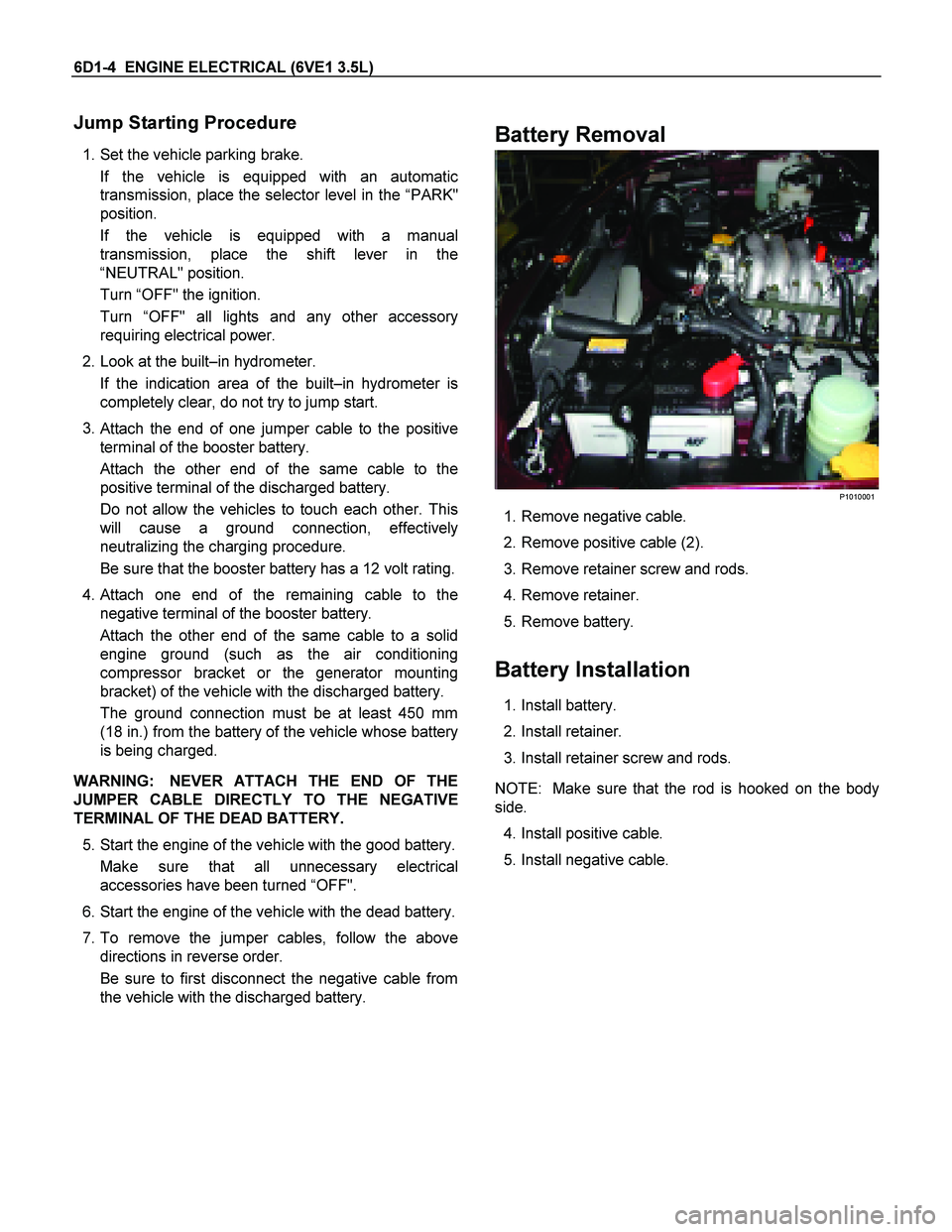
Battery Removal
P1010001
1. Remove negative cable.
2. Remove positive cable (2).
3. Remove retainer screw and rods.
4. Remove retainer.
5. Remove battery.
Battery Installation
1. Install battery.
2. Install retainer.
3. Install retainer screw and rods.
NOTE: Make sure that the rod is hooked on the body
side.
4. Install positive cable.
5. Install negative cable.
Page 2547 of 4264

ENGINE ELECTRICAL 6D1-5
Battery fluid is a highly corrosive acid.
Should battery fluid come in contact with your eyes, skin,
fabric, or a painted surface, immediately and thoroughly rinse
the affected area with clean tap water.
Never allow metal tools or jumper cables to come in contact
with the positive battery terminal, or any other metal surface of
the vahicle. This will protect against a short circuit.
Always keep batteries out of reach of young children.
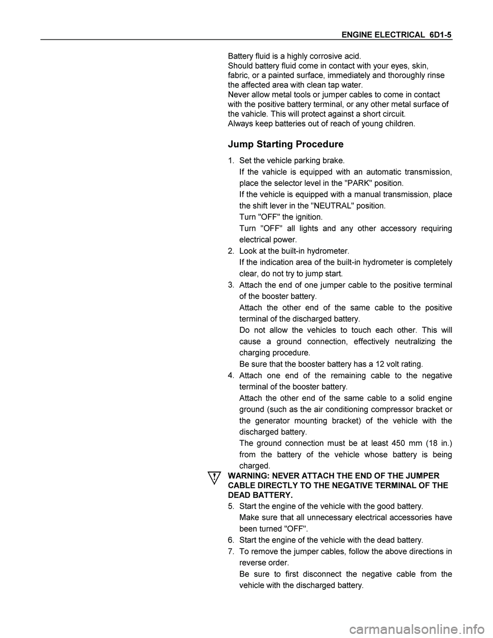
Jump Starting Procedure
1. Set the vehicle parking brake.
If the vahicle is equipped with an automatic transmission,
place the selector level in the "PARK" position.
If the vehicle is equipped with a manual transmission, place
the shift lever in the "NEUTRAL" position.
Turn "OFF" the ignition.
Turn "OFF" all lights and any other accessory requiring
electrical power.
2. Look at the built-in hydrometer.
If the indication area of the built-in hydrometer is completely
clear, do not try to jump start.
3.
Attach the end of one jumper cable to the positive terminal
of the booster battery.
Attach the other end of the same cable to the positive
terminal of the discharged battery.
Do not allow the vehicles to touch each other. This will
cause a ground connection, effectively neutralizing the
charging procedure.
Be sure that the booster battery has a 12 volt rating.
4.
Attach one end of the remaining cable to the negative
terminal of the booster battery.
Attach the other end of the same cable to a solid engine
ground (such as the air conditioning compressor bracket o
r
the generator mounting bracket) of the vehicle with the
discharged battery.
The ground connection must be at least 450 mm (18 in.)
from the battery of the vehicle whose battery is being
charged.
WARNING: NEVER ATTACH THE END OF THE JUMPER
CABLE DIRECTLY TO THE NEGATIVE TERMINAL OF THE
DEAD BATTERY.
5. Start the engine of the vehicle with the good battery.
Make sure that all unnecessary electrical accessories have
been turned "OFF".
6. Start the engine of the vehicle with the dead battery.
7. To remove the jumper cables, follow the above directions in
reverse order.
Be sure to first disconnect the negative cable from the
vehicle with the discharged battery.
Page 3349 of 4264

ANTITHEFT SYSTEM 11B – 3
Service Precaution
WARNING:
THIS VEHICLE HAS A SUPPLEMENTAL RESTRAINT SYSTEM (SRS). REFER TO THE SRS COMPONENT AND
WIRING LOCATION VIEW IN ORDER TO DETERMINE WHETHER YOU ARE PERFORMING SERVICE ON OR
NEAR THE SRS COMPONENTS OR THE SRS WIRING. WHEN YOU ARE PERFORMING SERVICE ON OR
NEAR THE SRS COMPONENTS OR THE SRS WIRING, REFER TO THE SRS SERVICE INFORMATION.
FAILURE TO FOLLOW WARNINGS COULD RESULT IN POSSIBLE AIR BAG DEPLOYMENT, PERSONAL
INJURY, OR OTHERWISE UNNEEDED SRS SYSTEM REPAIRS.
CAUTION:
Always use the correct fastener in the proper location. When you replace a fastener, use ONLY the exact
part number for that application. ISUZU will call out those fasteners that require a replacement after
removal. ISUZU will also call out the fasteners that require thread lockers or thread sealant. UNLESS
OTHERWISE SPECIFIED, do not use supplemental coatings (Paints, greases, or other corrosion inhibitors)
on threaded fasteners or fastener joint interfaces. Generally, such coatings adversely affect the fastener
torque and the joint clamping force, and may damage the fastener. When you install fasteners, use the
correct tightening sequence and specifications. Following these instructions can help you avoid damage
to parts and systems.
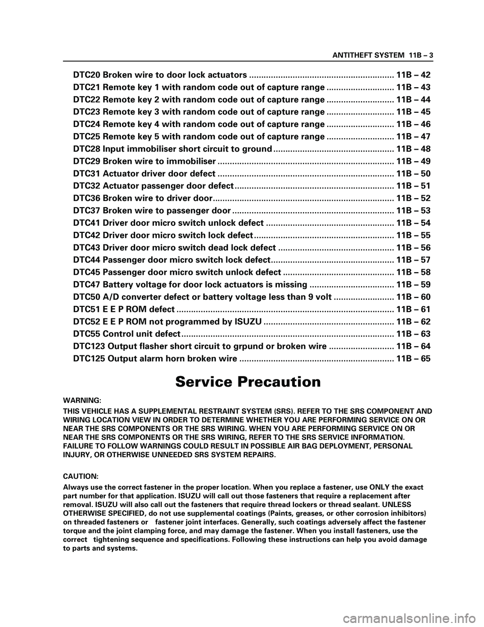
DTC20 Broken wire to door lock actuators ............................................................ 11B – 42
DTC21 Remote key 1 with random code out of capture range ............................ 11B – 43
DTC22 Remote key 2 with random code out of capture range ............................ 11B – 44
DTC23 Remote key 3 with random code out of capture range ............................ 11B – 45
DTC24 Remote key 4 with random code out of capture range ............................ 11B – 46
DTC25 Remote key 5 with random code out of capture range ............................ 11B – 47
DTC28 Input immobiliser short circuit to ground .................................................. 11B – 48
DTC29 Broken wire to immobiliser ......................................................................... 11B – 49
DTC31 Actuator driver door defect ......................................................................... 11B – 50
DTC32 Actuator passenger door defect .................................................................. 11B – 51
DTC36 Broken wire to driver door........................................................................... 11B – 52
DTC37 Broken wire to passenger door ................................................................... 11B – 53
DTC41 Driver door micro switch unlock defect ..................................................... 11B – 54
DTC42 Driver door micro switch lock defect .......................................................... 11B – 55
DTC43 Driver door micro switch dead lock defect ................................................ 11B – 56
DTC44 Passenger door micro switch lock defect................................................... 11B – 57
DTC45 Passenger door micro switch unlock defect .............................................. 11B – 58
DTC47 Battery voltage for door lock actuators is missing ................................... 11B – 59
DTC50 A/D converter defect or battery voltage less than 9 volt ......................... 11B – 60
DTC51 E E P ROM defect .......................................................................................... 11B – 61
DTC52 E E P ROM not programmed by ISUZU ...................................................... 11B – 62
DTC55 Control unit defect ........................................................................................ 11B – 63
DTC123 Output flasher short circuit to grpund or broken wire ........................... 11B – 64
DTC125 Output alarm horn broken wire ................................................................ 11B – 65
Page 3382 of 4264

11B – 36 ANTITHEFT SYSTEM
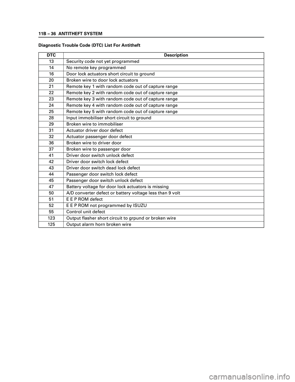
Diagnostic Trouble Code (DTC) List For Antitheft
DTC Description
13 Security code not yet programmed
14 No remote key programmed
16 Door lock actuators short circuit to ground
20 Broken wire to door lock actuators
21 Remote key 1 with random code out of capture range
22 Remote key 2 with random code out of capture range
23 Remote key 3 with random code out of capture range
24 Remote key 4 with random code out of capture range
25 Remote key 5 with random code out of capture range
28 Input immobiliser short circuit to ground
29 Broken wire to immobiliser
31 Actuator driver door defect
32 Actuator passenger door defect
36 Broken wire to driver door
37 Broken wire to passenger door
41 Driver door switch unlock defect
42 Driver door switch lock defect
43 Driver door switch dead lock defect
44 Passenger door switch lock defect
45 Passenger door switch unlock defect
47 Battery voltage for door lock actuators is missing
50 A/D converter defect or battery voltage less than 9 volt
51 E E P ROM defect
52 E E P ROM not programmed by ISUZU
55 Control unit defect
123 Output flasher short circuit to grpund or broken wire
125 Output alarm horn broken wire