Page 826 of 4264
8A-168 ELECTRICAL-BODY AND CHASSIS
TURN SIGNAL LIGHT AND HAZARD WARNING LIGHT
1. Turn signal light does not light on both sides (RH and LH)
Checkpoint Trouble Cause Countermeasure
Replace the flasher unit
Flasher unit malfunction
NG
Repair or replace the
combination switch
Turn signal switch continuity
between connector
5
B-60 - 6 B-60 and
5
B-60 - 7 B-60 when
turn signal switch operates
Short circuit between
connector 3
B-61 - 1 B-61
when turn signal switch
operates with starter switch
in “ON” position (Turn
signal light should be ON)
Poor switch point contact or
faulty switch
NG OK
Reinstall or replace fuse No.
EB-16 (10A)
Fuse No. EB-16 (10A, Fuse
box)
Poor fuse contact or blown
fuse
NG
OK OK
Repair open circuit or
connector contact
Continuity between
connector 2
B-61 -ground
(Should be continuity)
Open circuit or poor connector
contact
NG
Page 827 of 4264

ELECTRICAL-BODY AND CHASSIS 8A-169
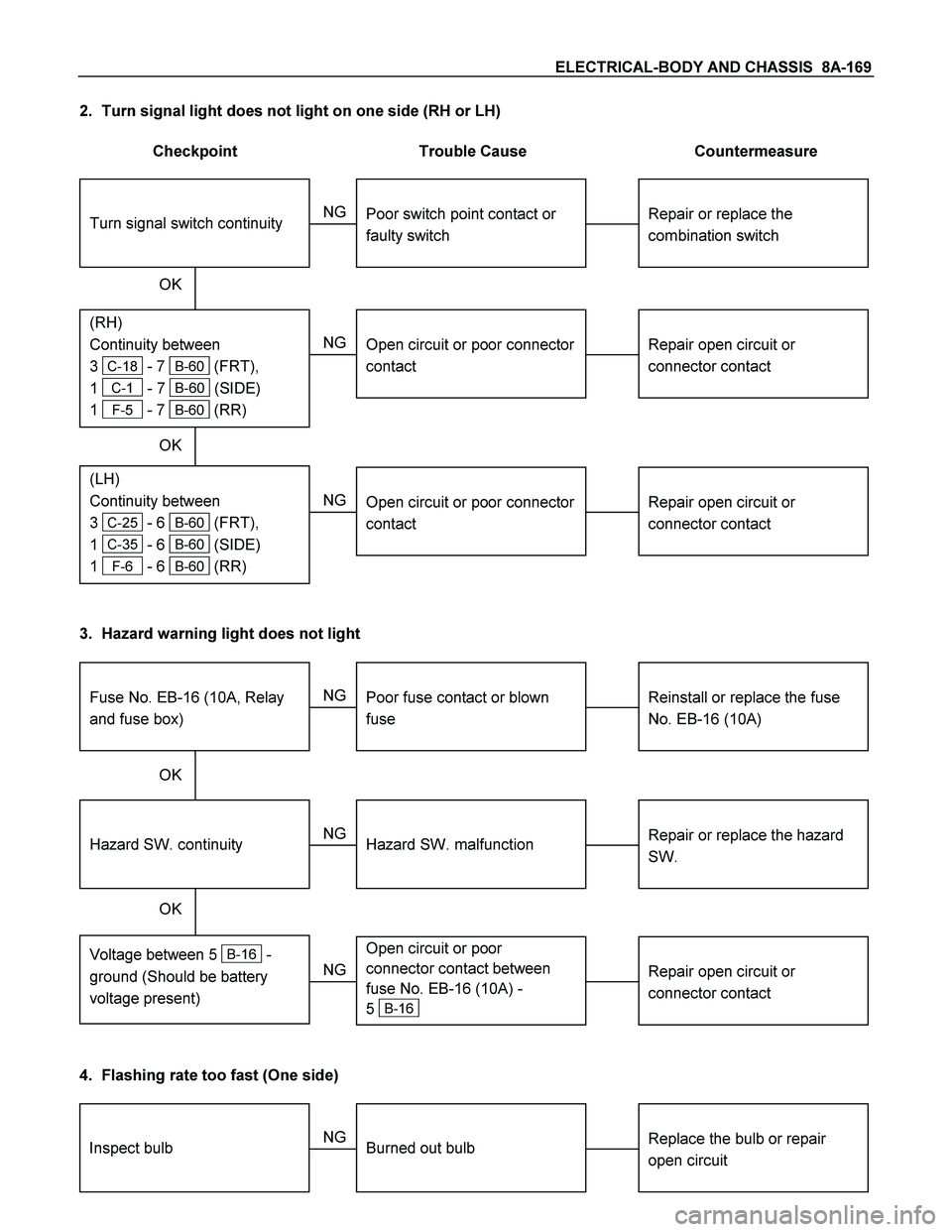
2. Turn signal light does not light on one side (RH or LH)
Checkpoint Trouble Cause Countermeasure
Repair open circuit or
connector contact
Open circuit or poor connector
contact
NG
(LH)
Continuity between
3
C-25 - 6 B-60 (FRT),
1
C-35 - 6 B-60 (SIDE)
1
F-6 - 6 B-60 (RR)
(RH)
Continuity between
3
C-18 - 7 B-60 (FRT),
1
C-1 - 7 B-60 (SIDE)
1
F-5 - 7 B-60 (RR)
Repair or replace the
combination switch
Turn signal switch continuity
Poor switch point contact or
faulty switch
NG
OK OK
Repair open circuit or
connector contact
Open circuit or poor connector
contact
NG
3. Hazard warning light does not light
Repair or replace the hazard
SW.
Hazard SW. malfunction
NG
Voltage between 5 B-16 -
ground (Should be battery
voltage present)
Hazard SW. continuity
Reinstall or replace the fuse
No. EB-16 (10A)
Fuse No. EB-16 (10A, Relay
and fuse box)
Poor fuse contact or blown
fuse
NG
OK OK
Repair open circuit or
connector contact
Open circuit or poor
connector contact between
fuse No. EB-16 (10A) -
5
B-16 NG
4. Flashing rate too fast (One side)
Replace the bulb or repair
open circuitInspect bulbBurned out bulb NG
Page 832 of 4264

8A-174 ELECTRICAL-BODY AND CHASSIS
Installation
Follow the removal procedure in the reverse order to install the
rear combination light.
Pay close attention to the important points mentioned in the
following paragraphs.
Bulb
Be absolutely sure that each bulb is correctly installed.
This will prevent a poor contact and an open circuit.
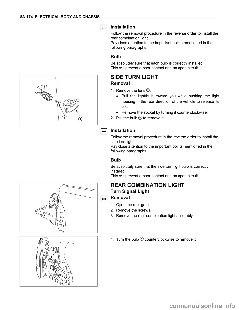
SIDE TURN LIGHT
Removal
1. Remove the lens 1.
� Pull the light/bulb toward you while pushing the ligh
t
housing in the rear direction of the vehicle to release its
lock.
� Remove the socket by turning it counterclockwise.
2. Pull the bulb
2 to remove it.
Installation
Follow the removal procedure in the reverse order to install the
side turn light.
Pay close attention to the important points mentioned in the
following paragraphs.
Bulb
Be absolutely sure that the side turn light bulb is correctly
installed.
This will prevent a poor contact and an open circuit.
REAR COMBINATION LIGHT
Turn Signal Light
Removal
1. Open the rear gate.
2. Remove the screws.
3. Remove the rear combination light assembly.
4. Turn the bulb 1 counterclockwise to remove it.
Page 834 of 4264
8A-176 ELECTRICAL-BODY AND CHASSIS
This illustration is based on RHD model
TURN SIGNAL SWITCH
Removal
1. Disconnect the battery ground cable.
2. Remove the steering wheel
1.
Refer to the “STEERING” Section of this Manual.
3. Remove the instruments panel lower cover
2.
4. Remove the steering column cover
3.
This illustration is based on RHD model
5. Disconnect the connector.
6. Remove the turn signal switch from the steering shaft.
Installation
Follow the removal procedure in the reverse order to install the
turn signal switch (lever).
Pay close attention to the important points mentioned in the
following paragraphs.
Connector
Be absolutely sure that the turn signal switch connector is
securely connected.
This will prevent a poor contact and at an open circuit.
Page 838 of 4264
8A-180 ELECTRICAL-BODY AND CHASSIS
3. Push the SRS air bag area1 and area2. At that time confirm
the audible noise of each stud.
4. Enable the SRS (Refer to “Enabling the SRS”in this
section).
INSPECTION AND REPAIR
Switch side Harness side
B-60 B-60
TURN SIGNAL SWITCH
Lighting Switch Connections
Terminal No.
SW position 5 6 7
Left
Neutral
Right
Turning
direction
Switch side
B-16
HAZARD WARNING FLASHER SWITCH
Hazard Warning Flasher Switch Connections
Terminal
No.
SW position
4
6
5
3
2
1
7
8
ON
OFF
Page 1055 of 4264
ELECTRICAL-BODY AND CHASSIS 8A-397
RTW38DSH001701
Turn Signal Test
Check the turn signal lamp lights up by operation of
Tech-2.
1. Turn the key “OFF”.
2. Turn the key “ON”.
3. Check the display and test menu.
4. Operate the Tech-2.
060R200289
Programming
Erase Remove Key
To erase remove control key code in the control unit.
1. Check the display of Tech-2 and press “Confirm”
key.
RTW38DSH001001
2. Enter security code.
3. Press “Not Okay” or “Okay” key.
Page 1100 of 4264

8B-2 CRUISE CONTROL SYSTEM
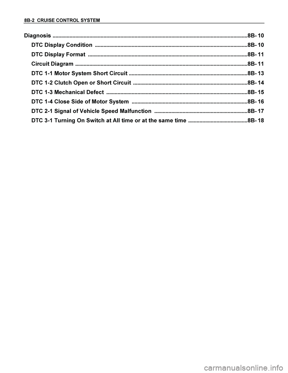
Diagnosis ..........................................................................................................................................8B- 10
DTC Display Condition ............................................................................................................8B- 10
DTC Display Format .................................................................................................................8B- 11
Circuit Diagram ..........................................................................................................................8B- 11
DTC 1-1 Motor System Short Circuit ....................................................................................8B- 13
DTC 1-2 Clutch Open or Short Circuit .................................................................................8B- 14
DTC 1-3 Mechanical Defect ....................................................................................................8B- 15
DTC 1-4 Close Side of Motor System ..................................................................................8B- 16
DTC 2-1 Signal of Vehicle Speed Malfunction ..................................................................8B- 17
DTC 3-1 Turning On Switch at All time or at the same time ..........................................8B- 18
Page 1101 of 4264

CRUISE CONTROL SYSTEM 8B-3
Service Precaution
WARNING: THIS VEHICLE HAS A SUPPLEMENTAL RESTRAIN SYSTEM (SRS). REFER TO THE SRS
COMPONENT AND WIRING LOCATION VIEW IN ORDER TO DETERMINE WHETHER YOU ARE
PERFORMING SERVICE ON OR NEAR THE SRS COMPONENTS OR THE SRS WIRING. WHEN YOU ARE
PERFORMING SERVICE ON OR NEAR THE SRS COMPONENTS OR THE SRS WIRING, REFER TO THE SRS
SERVICE INFORMATION. FAILURE TO FOLLOW WARNINGS COULD RESULT IN POSSIBLE AIR BAG
DEPLOYMENT, PERSONAL INJURY, OR OTHER WISE UNNEEDED SRS SYSTEM REPAIRS.
CAUTION: Always use the correct fastener in the proper location. When you replace a faster, use ONLY the
exact part number for that application. Dealer will call out those fasteners that require a replacement after
removal. Dealer will also call out the fasteners that require thread lockers or thread sealant. UNLESS
OTHERWISE SPECIFIED, do not use supplemental coatings (Paints, greases, or other corrosion inhibitors)
on threaded fasteners or fastener joint interfaces. Generally, such coatings adversely affect the fastener
torque and joint Clamping force, and may damaged the fastener. When you install fasteners, use the
correct tightening sequence and specifications. Following these instructions can help you avoid damage to
parts and systems.
General Description
The cruise control keeps the vehicle running at a fixed speed until a signal canceling this fixed speed is received.
When the main switch “AUTO CRUISE” is turned on with the vehicle in the running mode, the battery voltage is
applied to the control unit. When a signal from the control unit while the vehicle is in this state, the cruise control
actuator is activated to operate the system. Also, while the system is operating, the “AUTO CRUISE” indicator light
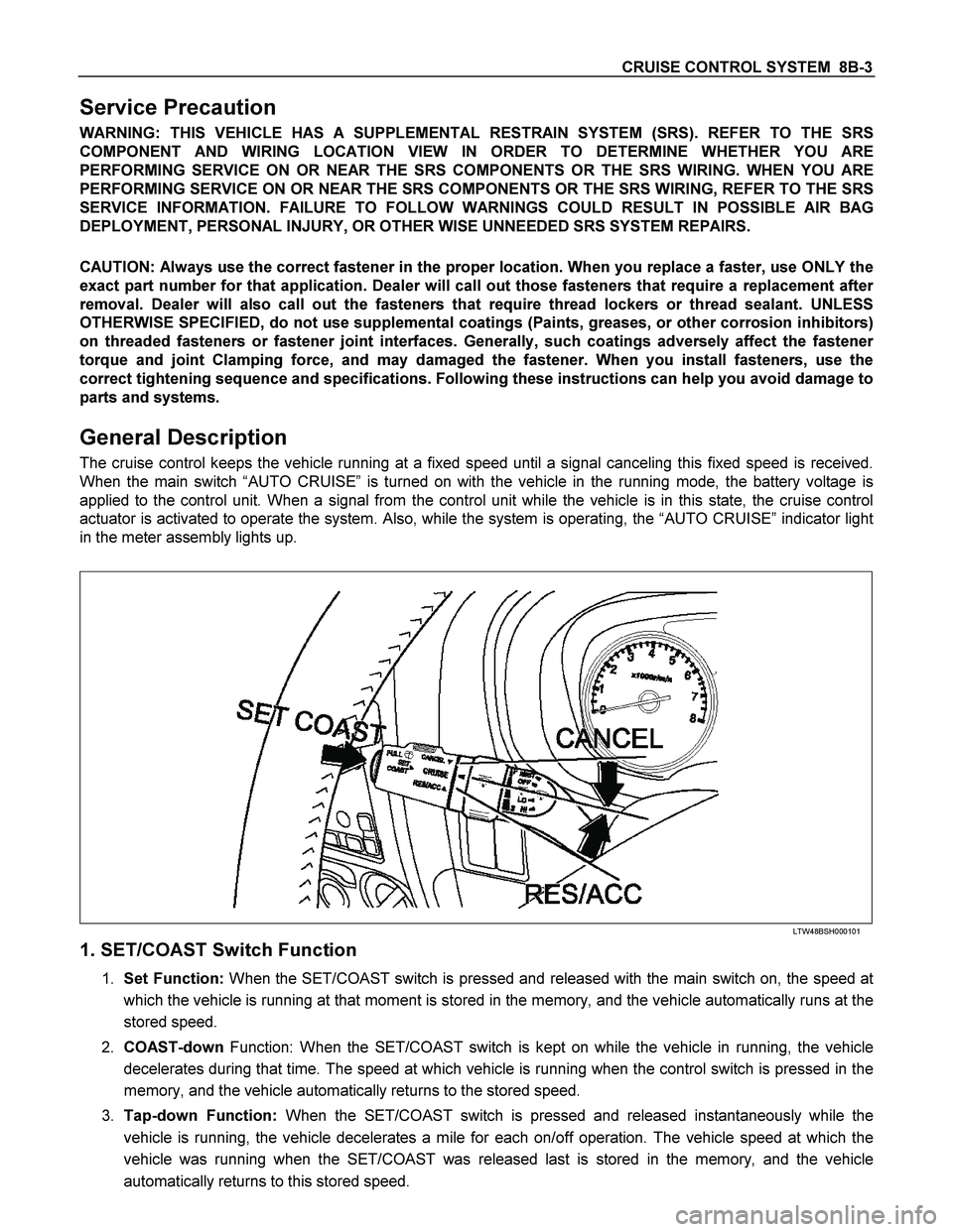
in the meter assembly lights up.
LTW48BSH000101
1. SET/COAST Switch Function
1. Set Function: When the SET/COAST switch is pressed and released with the main switch on, the speed at
which the vehicle is running at that moment is stored in the memory, and the vehicle automatically runs at the
stored speed.
2. COAST-down Function: When the SET/COAST switch is kept on while the vehicle in running, the vehicle
decelerates during that time. The speed at which vehicle is running when the control switch is pressed in the
memory, and the vehicle automatically returns to the stored speed.
3. Tap-down Function: When the SET/COAST switch is pressed and released instantaneously while the
vehicle is running, the vehicle decelerates a mile for each on/off operation. The vehicle speed at which the
vehicle was running when the SET/COAST was released last is stored in the memory, and the vehicle
automatically returns to this stored speed.