Page 3855 of 4264
UNIT REPAIR (AW30–40LE) 7A4–47
18. Remove the thrust washer.
Inspection and Repair
1. Check discs.
Using a micrometer, measure the thickness of the
discs.
Minimum thickness: 2.04 mm (0.0803 in)
If the thickness is less than the minimum, replace
the disc.
25 2RY 0 002 7
2. Check piston return spring
Using calipers, measure the free length of the return
spring.
Standard length: 15.8 mm (0.622 in)
25 2RY 0 002 8
3. Check OD direct clutch piston.
Check that the check ball is free by shaking the
piston. Check that the valve does not leak by
applying low-pressure compressed air.
25 2RY 0 0029
4. Check OD direct clutch drum bushings.
Using a dial indicator, measure the inside diameter
of the OD direct clutch drum bushings.
Maximum inside diameter: 27.11 mm (1.0673 in)
If the inside diameter is greater than the maximum,
replace the OD direct clutch drum.
25 2L10 0009
Page 3859 of 4264
UNIT REPAIR (AW30–40LE) 7A4–51
13. Install two plates and two discs then install the
flange, with the flat side facing downward.
2 52L10 001 3
14. Install snap ring.
2 52L10 001 4
15. Check piston stroke of OD direct clutch (C–0)
Place the oil pump onto the torque converter, and
then place the OD direct clutch assembly onto the
oil pump.
25 2L10 0005Using a dial indicator, measure the OD direct clutch
piston stroke by applying and releasing the
compressed air (390 – 780 kPa or 57 – 114 psi) as
shown.
Piston stroke: 1.85 – 2.15 mm (0.0729 – 0.0847 in)
If the piston stroke is not within specification,
replace the disc and recheck the piston stroke.
If the piston stroke is nonstandard, select another
flange.
Flange sizes
25 2L10 0016
Flange thickness Flange thickness
3.8 mm (0.150 in) 3.4 mm (0.134 in)
3.7 mm (0.146 in) 3.3 mm (0.130 in)
3.6 mm (0.142 in) 3.2 mm (0.126 in)
3.5 mm (0.138 in) 3.1 mm (0.122 in)
Page 3868 of 4264
7A4–60 UNIT REPAIR (AW30–40LE)
7. Place the direct clutch drum onto the OD support.
Holding the direct clutch piston by hand, apply
compressed air to the OD support to remove the
direct clutch piston.
Remove the direct clutch piston from direct clutch
drum.
24 8RY 0 003 0
8. Remove two O-rings from piston.
Inspection and Repair
1. Check piston return spring.
Using calipers, measure the free length of the return
spring.
Standard length: 21.3 mm (0.839 in)
24 7RY 0 003 4
2. Check discs.
Using micrometer, measure the thickness of the
discs.
Minimum thickness: 2.04 mm (0.0803 in)
If the thickness is less than the minimum, replace
the disc.
25 2RY 0 0027
3. Check direct clutch piston.
Check that check ball is free by shaking the piston.
Check that the valve does not leak by applying
low-pressure compressed air.
24 8RY 0 0031
Page 3871 of 4264
UNIT REPAIR (AW30–40LE) 7A4–63
Flange sizes
RUW 37A SH00 490 1
9. Coat the clutch drum thrust washer (plastic) with
petroleum jelly and install it onto the direct clutch.
NOTE: Make sure that the lugs fit into the cutout
portions on the direct clutch.
24 8RY 0 003 7
Align the flukes of discs in the direct clutch.
Install the direct clutch assembly onto the forward
clutch assembly.
Check that the distance from the direct clutch end to
the forward clutch end is 71.2 mm (2.803 in).
24 8RY 0 0038
Flange thickness Flange thickness
3.3 mm (0.130 in) 3.8 mm (0.150 in)
3.4 mm (0.134 in)—
3.5 mm (0.138 in) 4.0 mm (0.157 in)
3.6 mm (0.142 in)—
3.7 mm (0.146 in) 4.2 mm (0.165 in)
Page 4208 of 4264
7A4-34 UNIT REPAIR (JR405E)
08R&H36
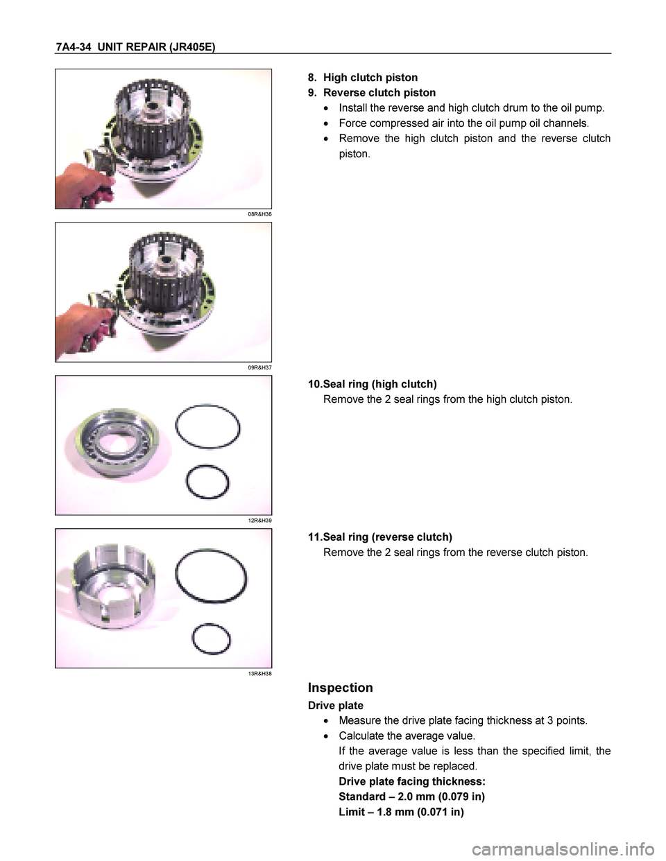
8. High clutch piston
9. Reverse clutch piston � Install the reverse and high clutch drum to the oil pump.
� Force compressed air into the oil pump oil channels.
� Remove the high clutch piston and the reverse clutch
piston.
09R&H37
12R&H39
10.Seal ring (high clutch)
Remove the 2 seal rings from the high clutch piston.
13R&H38
11.Seal ring (reverse clutch)
Remove the 2 seal rings from the reverse clutch piston.
Inspection
Drive plate
� Measure the drive plate facing thickness at 3 points.
� Calculate the average value.
If the average value is less than the specified limit, the
drive plate must be replaced.
Drive plate facing thickness:
Standard – 2.0 mm (0.079 in)
Limit – 1.8 mm (0.071 in)
Page 4212 of 4264

21R&H21
10.Dish plate, drive plates, driven plates, and retaining
plate Install the reverse clutch dish plate (1) the 2 driven plates
(2), the 2 drive plates (3")
7A4-38 UNIT REPAIR (JR405E)
21R&H21
10.Dish plate, drive plates, driven plates, and retaining
plate Install the reverse clutch dish plate (1) the 2 driven plates
(2), the 2 drive plates (3), and retaining plate (4).
248L300003
11.Snap ring
Install the snap ring.
NOTE:
If is careful in the attachment direction of dish plate (1).
22R&H35
�
Install the reverse and high clutch drum to the oil pump
assembly.
� Force compressed air (392 kPa/4.0 kg/cm
2) through the
oil pump oil passages to check high clutch operation.
If the clutch does not operate, the seal ring may be
damaged or the parts may have been installed in the
wrong order.
23CLEAR02
�
Measure the clearance between the high clutch retaining
plate and the snap ring.
If the clearance is outside the specified range, replace
the existing retaining plate with a new plate of the prope
r
size (thickness).
High clutch retaining plate and snap ring clearance
(A): 1.2~1.6 mm (0.047~0.063 in)
Available high clutch retaining plate thicknesses
4.6 mm (0.181 in)
4.8 mm (0.189 in)
Page 4214 of 4264
7A4-40 UNIT REPAIR (JR405E)
25CLEAR04
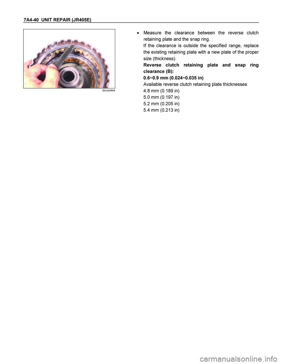
�
Measure the clearance between the reverse clutch
retaining plate and the snap ring.
If the clearance is outside the specified range, replace
the existing retaining plate with a new plate of the prope
r
size (thickness).
Reverse clutch retaining plate and snap ring
clearance (B):
0.6~0.9 mm (0.024~0.035 in)
Available reverse clutch retaining plate thicknesses
4.8 mm (0.189 in)
5.0 mm (0.197 in)
5.2 mm (0.205 in)
5.4 mm (0.213 in)
Page 4220 of 4264
7A4-46 UNIT REPAIR (JR405E)
18C&L-SUB28
19.Low one-way clutch
Remove the low one-way clutch.
19C&L-SUB29
20.Snap ring
Remove the snap ring from the low clutch drum.
20C&L-SUB31
21.Bearing
Remove the bearing.
Inspection
Drive plate
� Measure the drive plate facing thickness at 3 points.
� Calculate the average value.
If the average value is less than the specified limit, the
drive plate must be replaced.
Drive plate facing thickness:
Standard – 2.0 mm (0.079 in)
Limit – 1.8 mm (0.071 in)
Return spring
� Check the number of effective return spring coils.
If the number is less than the specified minimum, the
return spring must be replaced.
Effective return spring coils (standard): 9.9
� Measure the return spring outside diameter, free length,
and linear diameter.
If any of the measured values exceed the specified limit,
the return spring must be replaced.
Return spring measurements (standard):
Outside diameter – 9.7 mm (0.382 in)
 7A4–47
18. Remove the thrust washer.
Inspection and Repair
1. Check discs.
Using a micrometer, measure the thickness of the
discs.
Minimum thickness: 2.04 mm (0.0803 in)
If")
 7A4–51
13. Install two plates and two discs then install the
flange, with the flat side facing downward.
2 52L10 001 3
14. Install snap ring.
2 52L10 001 4
15. Check piston")

7. Place the direct clutch drum onto the OD support.
Holding the direct clutch piston by hand, apply
compressed air to the OD support to remove the
direct clutch pis")
 7A4–63
Flange sizes
RUW 37A SH00 490 1
9. Coat the clutch drum thrust washer (plastic) with
petroleum jelly and install it onto the direct clutch.
NOTE: Make sure that the")

18C&L-SUB28
19.Low one-way clutch
Remove the low one-way clutch.
19C&L-SUB29
20.Snap ring
Remove the snap ring from the low clutch drum.
20C&L-S")