Page 663 of 4264

ELECTRICAL-BODY AND CHASSIS 8A-5
NOTES FOR WORKING ON ELECTRICAL ITEMS
Battery
BATTERY CABLE
Disconnecting the Battery Cable
1. All switches should be "OFF" position.
2. Disconnect the battery ground cable.
3. Disconnect the battery positive cable.
CAUTION:
It is important that the battery ground cable be
disconnected first.
Disconnecting the battery positive cable first can result in
a short circuit.
Connecting the Battery Cable
Follow the disconnecting procedure in the reverse order to
connect the battery cables.
CAUTION:
Clean the battery terminal and apply light coat of grease to
prevent terminal corrosion.
CONNECTOR HANDLING
Disconnecting the Connectors
Some connectors have a tang lock to hold the connectors
together during vehicle operation.
Some tang locks are released by pulling them towards you
1.
Other tang locks are released by pressing them forward
2.
Determine which type of tang lock is on the connector being
handled.
Firmly grasp both sides (male and female) of the connector.
Release the tang lock and carefully pull the two halves of the
connector apart.
Never pull on the wires to separate the connectors.
This will result in wire breakage.
Page 746 of 4264
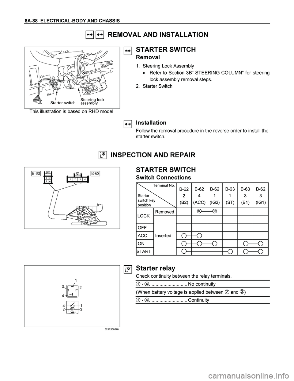
8A-88 ELECTRICAL-BODY AND CHASSIS
REMOVAL AND INSTALLATION
This illustration is based on RHD model
STARTER SWITCH
Removal
1. Steering Lock Assembly
� Refer to Section 3B" STEERING COLUMN" for steering
lock assembly removal steps.
2. Starter Switch
Installation
Follow the removal procedure in the reverse order to install the
starter switch.
INSPECTION AND REPAIR
STARTER SWITCH
Switch Connections
Terminal No.
Starter
switch key
position B-62
2
(B2)B-62
4
(ACC)B-62
1
(IG2) B-63
1
(ST) B-63
3
(B1)B-62
3
(IG1)
Removed
OFF
ACC Inserted
ON
START
LOCK
825R300046
Starter relay
Check continuity between the relay terminals.
1 - 4............................. No continuity
(When battery voltage is applied between 2 and 3)
1 - 4............................. Continuity
Page 787 of 4264

ELECTRICAL-BODY AND CHASSIS 8A-129
Installation
Follow the removal procedure in the reverse order to install the
headlight.
Pay close attention to the important points mentioned in the
following paragraphs.
Connector
Be absolutely sure that the headlight connector is securely
connected.
This will prevent a contact and an open circuit.
This illustration is based on RHD model
LIGHTING SWITCH
Removal
1. Disconnect the battery ground cable.
2. Remove the steering wheel
1.
Refer to the “STEERING” Section of this manual.
3. Remove the Instrument panel lower cover
2.
4. Remove the steering column cover
3.
This illustration is based on RHD model
5. Disconnect the connector.
6. Remove the lighting switch from the steering shaft.
Installation
Follow the removal procedure in the reverse order to install the
lighting switch.
Pay close attention to the important points mentioned in the
following paragraphs.
Connector
Be absolutely sure that the lighting switch connector is securely
connected.
This will prevent a poor contact and an open circuit.
Wire Harness
Do not pinch the wire harnesses between the cluster and the
meter hood during the cluster installation procedure.
Wire damage will result.
Page 789 of 4264

ELECTRICAL-BODY AND CHASSIS 8A-131
LICENSE PLATE LIGHT
Removal
1. Remove the lens cover 1 and the connector 2.
2. Pull the bulb
3 to remove it.
Installation
Follow the removal procedure in the reverse order to install the
license plate light.
Pay close attention to the important points mentioned in the
following paragraphs.
Bulb
Be absolutely sure that the license plate light bulb is correctly
installed.
This will prevent a poor contact and open circuit.
HEADLIGHT BEAM SWITCH
(COMBINATION SWITCH)
Removal
1. Disconnect the battery ground cable.
2. Remove the screws on the lower part of the steering wheel.
3. Remove the horn pad.
4. Remove the wiring connector.
5. Remove the steering wheel fixing nuts.
6. Remove the steering wheel.
Refer to the "STEERING" Section of this manual.
7. Remove the Instrument panel lower cover.
8. Remove the steering column cover.
9. Disconnect the connector.
10. Remove the headlight beam switch (lever) from the steering
shaft (combination switch).
Installation
Follow the removal procedure in the reverse order to install the
headlight beam switch (lever).
Pay close attention to the important points mentioned in the
following paragraphs.
Connector
Be absolutely sure that the headlight beam switch connector is
securely connected.
This will prevent a poor contact and an open circuit.
Page 793 of 4264
ELECTRICAL-BODY AND CHASSIS 8A-135
LIGHTING RELAY, TAIL RELAY
Check continuity between the relay terminals.
2 - 1............................. No continuity
(When battery voltage is applied between 3 and 4)
2 - 1............................. Continuity
GLOVE BOX ILLUMINATION
Removal
1. Remove the bulb cover 1.
2. Remove the bulb
2.
Installation
To install, follow the removal steps in the reverse order.
POWER/3rd START SW
Removal
� Refer to the “Front consol” Section 10 of this manual.
1. Disconnect the battery ground cable.
2. Remove the power/3rd start switch.
3. Remove the bulb.
Installation
To install, follow the removal steps in the reverse order.
A/T LEVER LIGHT BULB
Removal
� Refer to the “Front consol” Section 10 of this manual.
1. Remove the A/T lever cover.
2. Remove the light bulb
1.
Installation
To install, follow the removal steps in the reverse order.
Page 800 of 4264
8A-142 ELECTRICAL-BODY AND CHASSIS
FRONT FOG LIGHT
Removal
1. Remove the radiator grille.
2. Remove the front bumper
3. Disconnect the fog light connector.
4. Remove the fog light.
5. Remove the bulb from the socket.
� Remove the socket by turning it counterclockwise.
Installation
Follow the removal procedure in the reverse order to install the
fog light.
Pay close attention to the important points mentioned in the
following paragraphs.
Bulb
Be absolutely sure that the fog light bulb is correctly installed.
This will prevent a poor contact and open circuit.
FRONT FOG LIGHT ADJUSTMENT
Vertical Adjustment
Turn the adjusting screw (1) with a screwdriver to adjust the
aim of the fog light vertically.
RTU4Z0SH000601
FRONT FOG & REAR FOG SWITCH
Page 801 of 4264
ELECTRICAL-BODY AND CHASSIS 8A-143
RTW48ASH000401
Inspection
Check to see if there is any continuity between the terminals of
the front fog light switch.
Replace the switch when the result of inspection is found
abnormal.
Removal
Preparation:
Disconnect the battery ground cable.
1. Ventilation grille
2. Harness connector
3. Front fog light & Rear fog light switch
To remove the switch, push the lock from the back side of
the cluster assembly.
4. Remove the bulb.
RTW48ASH000301
Installation
To install, follow the removal steps in the reverse noting the
following point.
1. Push in the switch with your fingers until it locks securely.
Page 806 of 4264

8A-148 ELECTRICAL-BODY AND CHASSIS
RTW48ASH000701
REAR FOG LIGHT
Removal
1. Remove the screws 1.
2. Remove the lens cover
2.
3. Rear fog push turn the bulb
3 counterclockwise to
disconnect it from the light housing.
Installation
Follow the removal procedure in the reverse order to install the
rear fog light.
Pay close attention to the important points mentioned in the
following paragraphs.
Bulb
Be absolutely sure that the license plate light bulb is correctly
installed.
This will prevent a poor contact and open circuit.
RTU4Z0SH000601
FRONT FOG & RR FOG SWITCH
RTW48ASH000401
Inspection
Check to see if there is any continuity between the terminals of
the leveling switch.
Replace the switch when the result of inspection is found
abnormal.
Removal
Preparation:
Disconnect the battery ground cable.
1. Ventilation grille
2. Harness connector
3. Front fog light & Rear fog light switch
To remove the switch, push the lock from the back side of
the cluster assembly.
4. Remove the bulb.