Page 3779 of 4264
ON-VEHICLE SERVICE (AW30 –40LE) 7A3-23
Neutral Start Switch (Mode Switch)
Inspection
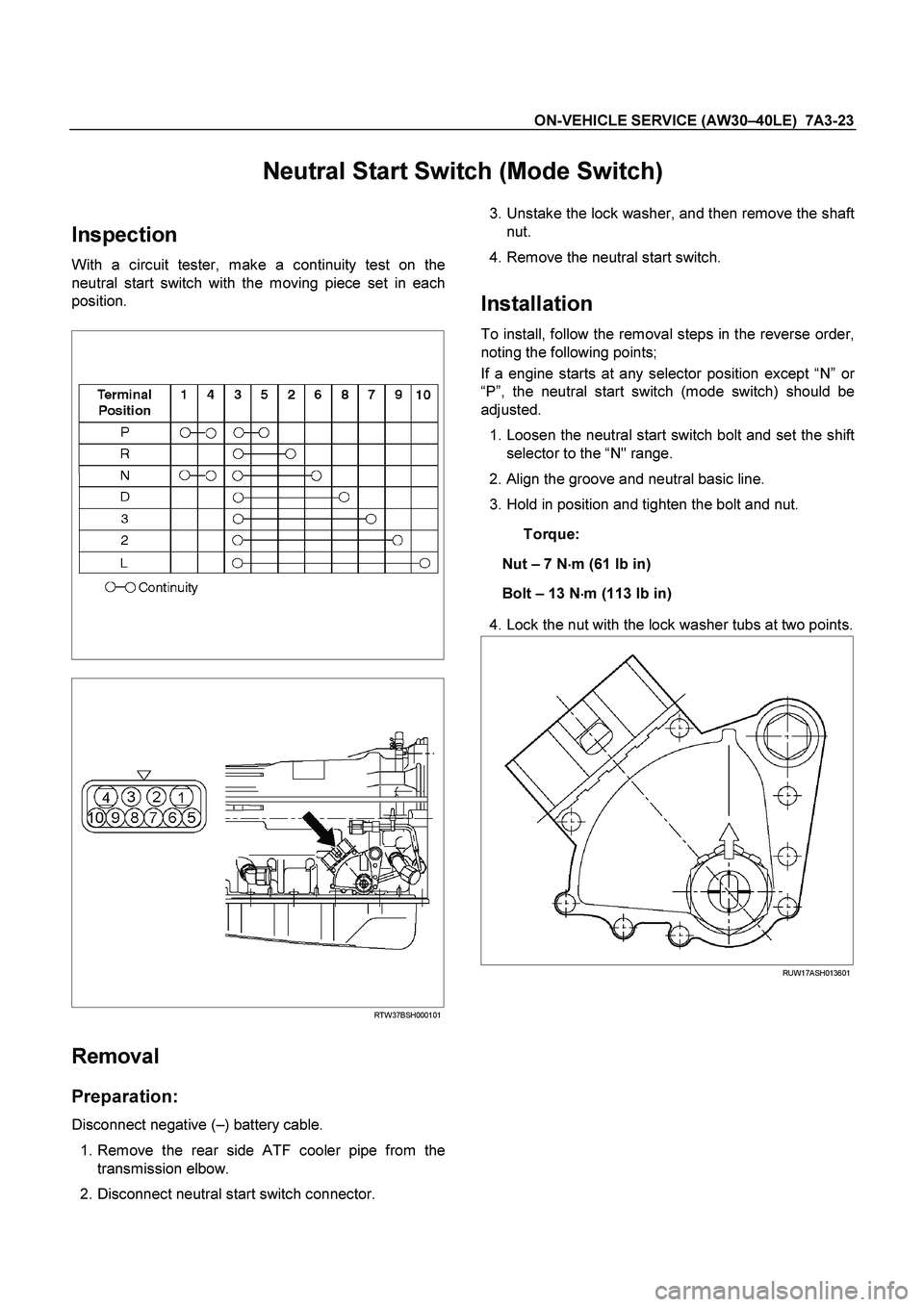
With a circuit tester, make a continuity test on the
neutral start switch with the moving piece set in each
position.
RTW37BSH000101
Removal
Preparation:
Disconnect negative ( –) battery cable.
1. Remove the rear side ATF cooler pipe from the
transmission elbow.
2. Disconnect neutral start switch connector.
3. Unstake the lock washer, and then remove the shaft
nut.
4. Remove the neutral start switch.
Installation
To install, follow the removal steps in the reverse order,
noting the following points;
If a engine starts at any selector position except “N ” o
r
“ P ”, the neutral start switch (mode switch) should be
adjusted.
1. Loosen the neutral start switch bolt and set the shift
selector to the “N" range.
2. Align the groove and neutral basic line.
3. Hold in position and tighten the bolt and nut.
Torque:
Nut – 7 N �
��
�
m (61 Ib in)
Bolt – 13 N �
��
�
m (113 Ib in)
4. Lock the nut with the lock washer tubs at two points.
RUW17ASH013601
Page 3952 of 4264
7A1-6 CONSTRUCTION AND FUNCTION
ELECTRONIC CONTROL COMPONENTS LOCATION
4WD Only 4WD Only
Instrument panel (Meter)
Speed meter (2WD Only)
Shift position indicator lamp
POWER DRIVE, 3rd START
indicator lamp
A/T OIL TEMP indicator lamp
CHECK TRANS indicator lam
p
Brake pedal
Brake Switch
Select lever
Power Drive
, 3rd Start select switch
Transmission Control Module (TCM)
Electrical source
Ignition
Battery voltage
Speed sensor
Turbine sensor
Inhibitor switch
ATF thermo sensor
High clutch oil pressure switch
2-4 brake oil pressure switch
Low & Reverse brake oil pressure
switch
Line pressure solenoid
Low clutch solenoid
High clutch solenoid
2-4 brake solenoid
Low & Reverse brake solenoid
Lock-up solenoid
Transmission
Transfer Control Module
Transfer
4L mode switch
Engine
Engine speed sensor
Throttle Position Sensor
Engine Control Module (ECM)
Data link connector
Page 3961 of 4264
CONSTRUCTION AND FUNCTION 7A1-15
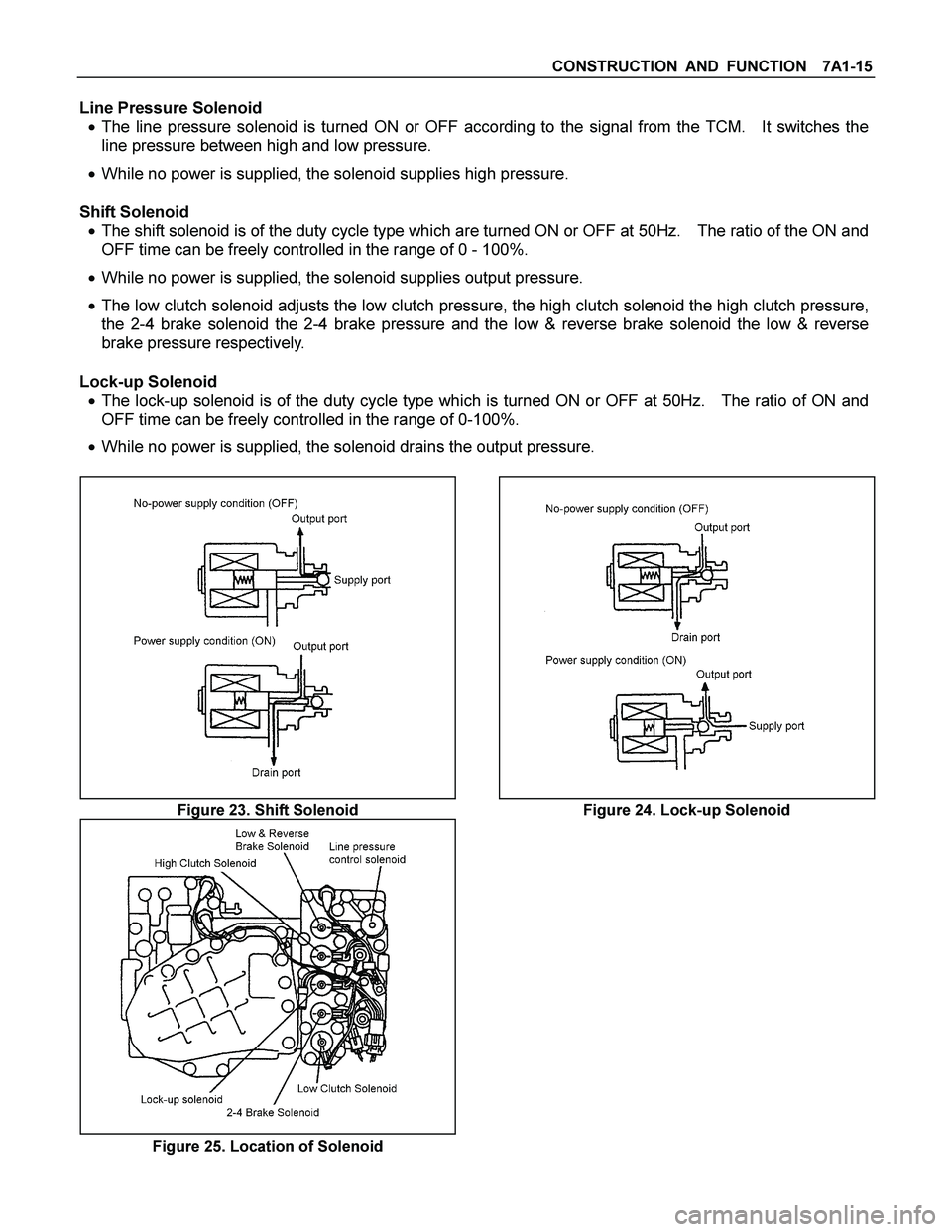
Line Pressure Solenoid
� The line pressure solenoid is turned ON or OFF according to the signal from the TCM. It switches the
line pressure between high and low pressure.
� While no power is supplied, the solenoid supplies high pressure.
Shift Solenoid
� The shift solenoid is of the duty cycle type which are turned ON or OFF at 50Hz. The ratio of the ON and
OFF time can be freely controlled in the range of 0 - 100%.
� While no power is supplied, the solenoid supplies output pressure.
� The low clutch solenoid adjusts the low clutch pressure, the high clutch solenoid the high clutch pressure,
the 2-4 brake solenoid the 2-4 brake pressure and the low & reverse brake solenoid the low & reverse
brake pressure respectively.
Lock-up Solenoid
� The lock-up solenoid is of the duty cycle type which is turned ON or OFF at 50Hz. The ratio of ON and
OFF time can be freely controlled in the range of 0-100%.
� While no power is supplied, the solenoid drains the output pressure.
Figure 23. Shift Solenoid Figure 24. Lock-up Solenoid
Figure 25. Location of Solenoid
Page 3962 of 4264
7A1-16 CONSTRUCTION AND FUNCTION
Control Valve Fail-safe Function
� To prevent interlocking due to engagement of more than three clutches and brakes at the same time, the
2-4 brake fail-safe valve A and B, and the low & reverse brake fail-safe valve A and B are provided.
� When oil pressure is generated in the high clutch and the low clutch, the 2-4 brake solenoid is turned ON
to drain the oil pressure applied to the 2-4 brake.
� When oil pressure is generated in the high clutch or 2-4 brake, the low & reverse brake solenoid is turned
ON to drain the oil pressure applied to the low & reverse brake.
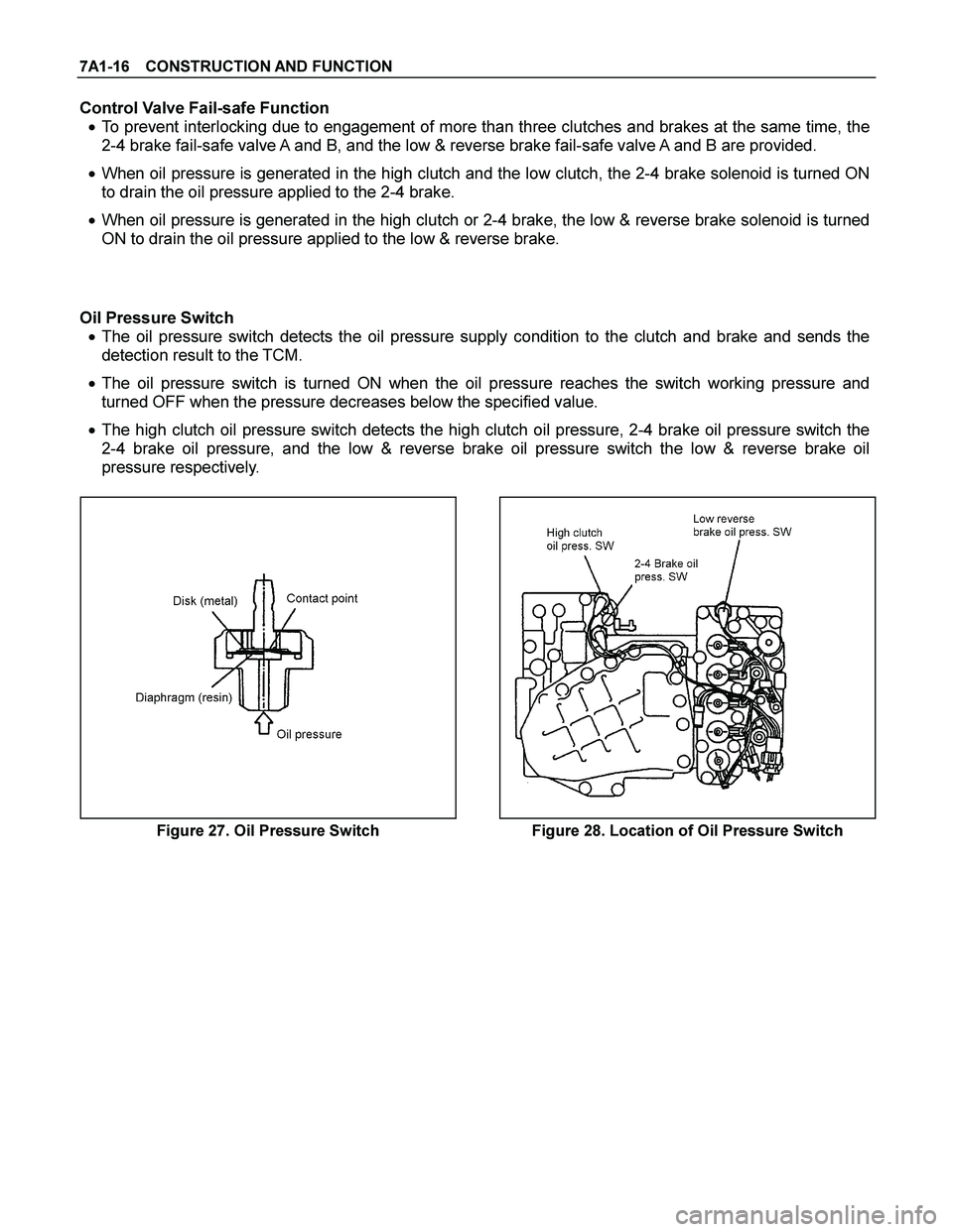
Oil Pressure Switch
� The oil pressure switch detects the oil pressure supply condition to the clutch and brake and sends the
detection result to the TCM.
� The oil pressure switch is turned ON when the oil pressure reaches the switch working pressure and
turned OFF when the pressure decreases below the specified value.
� The high clutch oil pressure switch detects the high clutch oil pressure, 2-4 brake oil pressure switch the
2-4 brake oil pressure, and the low & reverse brake oil pressure switch the low & reverse brake oil
pressure respectively.
Figure 27. Oil Pressure Switch Figure 28. Location of Oil Pressure Switch
Page 3964 of 4264
7A1-18 CONSTRUCTION AND FUNCTION
Terminal Assembly
Pin No. Connected to Connected TCMPin No.
6 Line Pressure Solenoid B23
12 Low & Reverse Brake Oil Pressure Switch B12
5 Low & Reverse Brake Duty Solenoid B6
11 Ground Return B22
4 Lock-up Duty Solenoid B17
10 High Clutch Duty Solenoid B8
3 Low Clutch Duty Solenoid B9
9 2-4 Brake Duty Solenoid B7
2 Oil Thermo Sensor B4
8 Oil Thermo Sensor Ground B14
1 High Clutch Oil Pressure Switch B20
7 2-4 Brake Oil Pressure Switch B1
123456
891011127
Terminal Assembly Inhibitor Switch
Figure 31. Pin Assignment Figure 32. Location of Terminal Assembly
Page 3971 of 4264
CONSTRUCTION AND FUNCTION 7A1-25
TRANSMISSION CONTROL MODULE (TCM)
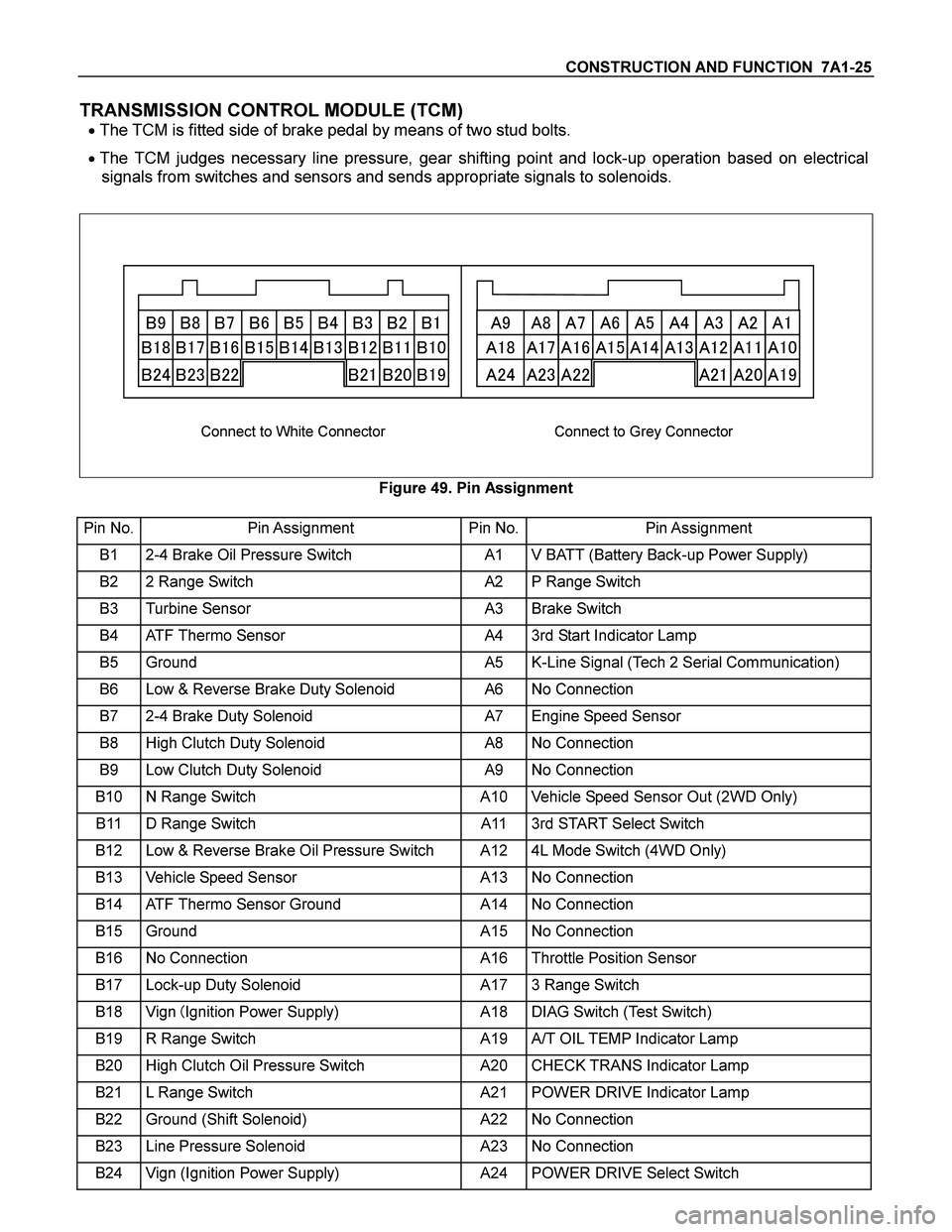
� The TCM is fitted side of brake pedal by means of two stud bolts.
� The TCM judges necessary line pressure, gear shifting point and lock-up operation based on electrical
signals from switches and sensors and sends appropriate signals to solenoids.
�� �� �� �� �� �� �� � �
�� �� �� �� �� �� �� � �
�
� �
� �
� �
� �
� �
� �
�
�
� �
� �
� �
� �
� �
� �
� �
�
�
�
� � � � � �
� � �
� � � � � � �
� � �
�
Connect to White Connector Connect to Grey Connector
Figure 49. Pin Assignment
Pin No. Pin Assignment Pin No.Pin Assignment
B1 2-4 Brake Oil Pressure Switch A1 V BATT (Battery Back-up Power Supply)
B2 2 Range Switch A2 P Range Switch
B3 Turbine Sensor A3 Brake Switch
B4 ATF Thermo Sensor A4 3rd Start Indicator Lamp
B5 Ground A5 K-Line Signal (Tech 2 Serial Communication)
B6 Low & Reverse Brake Duty Solenoid A6 No Connection
B7 2-4 Brake Duty Solenoid A7 Engine Speed Sensor
B8 High Clutch Duty Solenoid A8 No Connection
B9 Low Clutch Duty Solenoid A9 No Connection
B10 N Range Switch A10 Vehicle Speed Sensor Out (2WD Only)
B11 D Range Switch A11 3rd START Select Switch
B12 Low & Reverse Brake Oil Pressure Switch A12 4L Mode Switch (4WD Only)
B13 Vehicle Speed Sensor A13 No Connection
B14 ATF Thermo Sensor Ground A14 No Connection
B15 Ground A15 No Connection
B16 No Connection A16 Throttle Position Sensor
B17 Lock-up Duty Solenoid A17 3 Range Switch
B18 Vign �Ignition Power Supply) A18 DIAG Switch (Test Switch)
B19 R Range Switch A19 A/T OIL TEMP Indicator Lamp
B20 High Clutch Oil Pressure Switch A20 CHECK TRANS Indicator Lamp
B21 L Range Switch A21 POWER DRIVE Indicator Lamp
B22 Ground (Shift Solenoid) A22 No Connection
B23 Line Pressure Solenoid A23 No Connection
B24 Vign (Ignition Power Supply) A24 POWER DRIVE Select Switch
Page 3975 of 4264
CONSTRUCTION AND FUNCTION 7A1-29
CONTROL ITEM, INPUT AND OUTPUT
Control item
Item
Line
pressure
control
Gear
shift
control
Shift
pattern
selection
Lock-up
controlDirect
electronic
shift
control
(DECS)
Learning
control
Fail-safe
function
Self-
diagnosis
function
Speed sensor
Turbine sensor
Engine speed sensor
Brake switch
Inhibitor switch
Mode select switch
4L switch (4WD Only)
ATF thermo sensor
High clutch oil pressure switch
2-4 brake oil pressure switch
Low & Reverse brake oil pressure
switch
Input
Throttle position sensor
Line pressure solenoid
Low clutch solenoid
High clutch solenoid
2-4 brake solenoid
Low & Reverse brake solenoid
Lock-up solenoid
Shift pattern indicator lamp
ATF temperature indicator lamp
Output
Check trans indicator lamp
Page 3977 of 4264
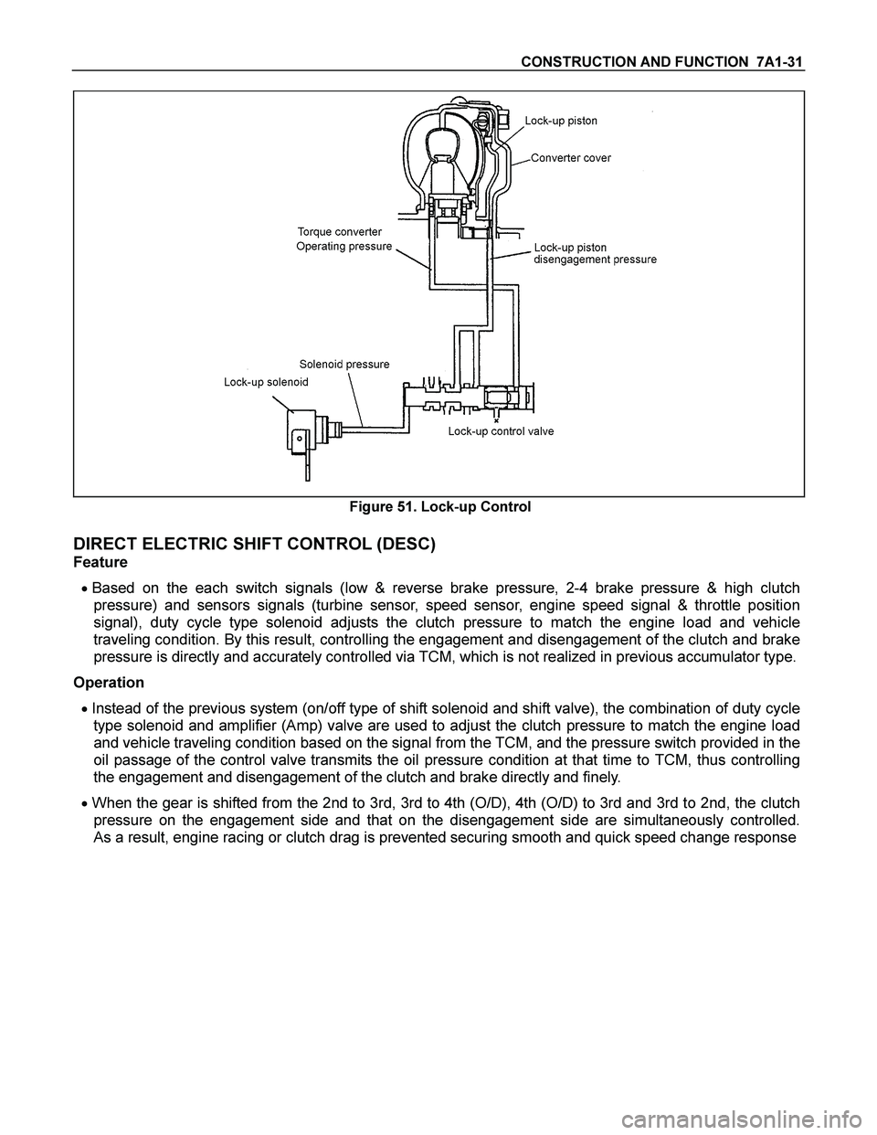
CONSTRUCTION AND FUNCTION 7A1-31
Figure 51. Lock-up Control
DIRECT ELECTRIC SHIFT CONTROL (DESC)
Feature
� Based on the each switch signals (low & reverse brake pressure, 2-4 brake pressure & high clutch
pressure) and sensors signals (turbine sensor, speed sensor, engine speed signal & throttle position
signal), duty cycle type solenoid adjusts the clutch pressure to match the engine load and vehicle
traveling condition. By this result, controlling the engagement and disengagement of the clutch and brake
pressure is directly and accurately controlled via TCM, which is not realized in previous accumulator type.
Operation
� Instead of the previous system (on/off type of shift solenoid and shift valve), the combination of duty cycle
type solenoid and amplifier (Amp) valve are used to adjust the clutch pressure to match the engine load
and vehicle traveling condition based on the signal from the TCM, and the pressure switch provided in the
oil passage of the control valve transmits the oil pressure condition at that time to TCM, thus controlling
the engagement and disengagement of the clutch and brake directly and finely.
� When the gear is shifted from the 2nd to 3rd, 3rd to 4th (O/D), 4th (O/D) to 3rd and 3rd to 2nd, the clutch
pressure on the engagement side and that on the disengagement side are simultaneously controlled.
As a result, engine racing or clutch drag is prevented securing smooth and quick speed change response