Page 4056 of 4264
7A2 -64 DIAGNOSIS (JR405E)
DTC P1853 (Flash Code 26) Low & Reverse Brake Pressure Switch Failure
Control Valve
TCM
B1
B12
B20
RED/YEL
WHT/BLK
2-4 Brake Pressure SW
Terminal
Assembly
YEL
E54 (7)
(12)
(1)H23 (12)
(10)C95 (1)
(12)
(20)
RED/YEL
YEL
WHT/BLK
L&R Brake Pressure SW
High Clutch Pressure SWH22 (8)
Pre-setting Condition:
� No gear shifting.
� No Check Trans indicator lamp.
� No system voltage failure.
� No inhibitor switch failure.
� Low & reverse brake duty solenoid 0 or 100 %.
� ATF temperature more than 60 �C.
� ATF input voltage more than 0.1V.
� Engine speed more than 500 rpm.
Page 4057 of 4264
DIAGNOSIS (JR405E) 7A2-65
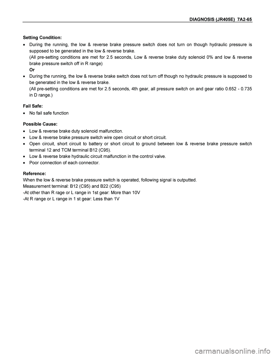
Setting Condition:
� During the running, the low & reverse brake pressure switch does not turn on though hydraulic pressure is
supposed to be generated in the low & reverse brake.
(All pre-setting conditions are met for 2.5 seconds, Low & reverse brake duty solenoid 0% and low & reverse
brake pressure switch off in R range)
Or
� During the running, the low & reverse brake switch does not turn off though no hydraulic pressure is supposed to
be generated in the low & reverse brake.
(All pre-setting conditions are met for 2.5 seconds, 4th gear, all pressure switch on and gear ratio 0.652 - 0.735
in D range.)
Fail Safe:
� No fail safe function
Possible Cause:
� Low & reverse brake duty solenoid malfunction.
� Low & reverse brake pressure switch wire open circuit or short circuit.
� Open circuit, short circuit to battery or short circuit to ground between low & reverse brake pressure switch
terminal 12 and TCM terminal B12 (C95).
� Low & reverse brake hydraulic circuit malfunction in the control valve.
� Poor connection of each connector.
Reference:
When the low & reverse brake pressure switch is operated, following signal is outputted.
Measurement terminal: B12 (C95) and B22 (C95)
-At other than R rage or L range in 1st gear: More than 10V
-At R range or L range in 1 st gear: Less than 1V
Page 4058 of 4264
7A2-66 DIAGNOSIS (JR405E)
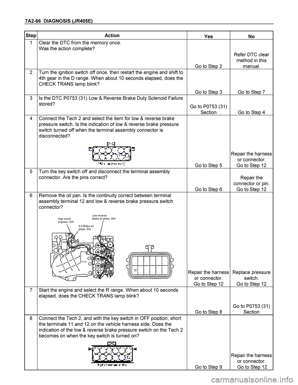
Step Action Yes No
1 Clear the DTC from the memory once.
Was the action complete?
Go to Step 2
Refer DTC clear
method in this
manual.
2 Turn the ignition switch off once, then restart the engine and shift to
4th gear in the D range. When about 10 seconds elapsed, does the
CHECK TRANS lamp blink?
Go to Step 3 Go to Step 7
3 Is the DTC P0753 (31) Low & Reverse Brake Duty Solenoid Failure
stored? Go to P0753 (31)
Section Go to Step 4
4 Connect the Tech 2 and select the item for low & reverse brake
pressure switch. Is the indication of low & reverse brake pressure
switch turned off when the terminal assembly connector is
disconnected?
Go to Step 5
Repair the harness
or connector.
Go to Step 12
5 Turn the key switch off and disconnect the terminal assembly
connector. Are the pins correct?
Go to Step 6
Repair the
connector or pin.
Go to Step 12
6 Remove the oil pan. Is the continuity correct between terminal
assembly terminal 12 and low & reverse brake pressure switch
connector?
12
Repair the harness
or connector.
Go to Step 12
Replace pressure
switch.
Go to Step 12
7 Start the engine and select the R range. When about 10 seconds
elapsed, does the CHECK TRANS lamp blink?
Go to Step 8
Go to P0753 (31)
Section
8 Connect the Tech 2, and with the key switch in OFF position, short
the terminals 11 and 12 on the vehicle harness side. Does the
indication of the low & reverse brake pressure switch on the Tech 2
becomes on when the key switch is turned on?
Go to Step 9
Repair the harness
or connector.
Go to Step 12
Page 4059 of 4264
DIAGNOSIS (JR405E) 7A2-67
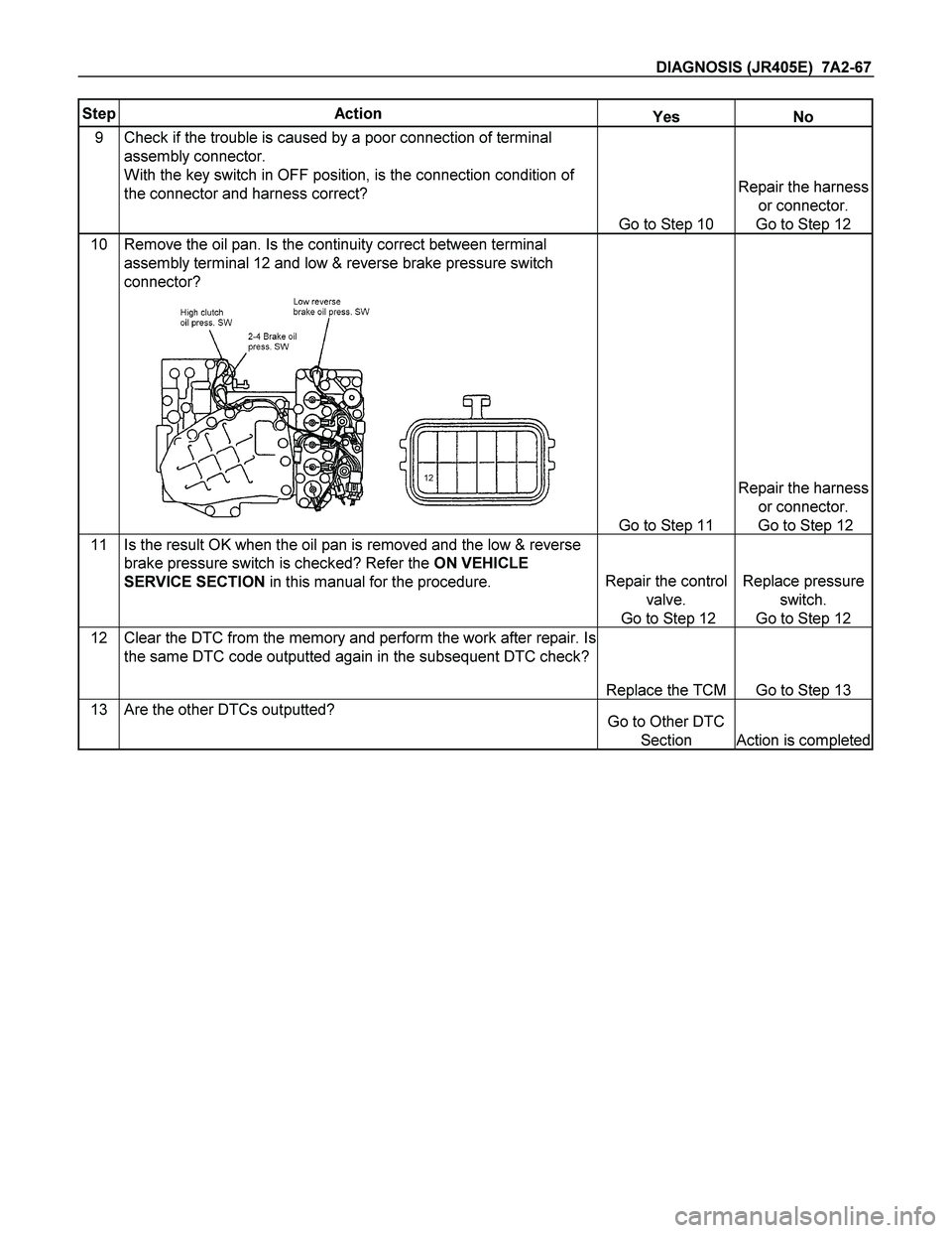
Step Action Yes No
9 Check if the trouble is caused by a poor connection of terminal
assembly connector.
With the key switch in OFF position, is the connection condition of
the connector and harness correct?
Go to Step 10
Repair the harness
or connector.
Go to Step 12
10 Remove the oil pan. Is the continuity correct between terminal
assembly terminal 12 and low & reverse brake pressure switch
connector?
12
Go to Step 11
Repair the harness
or connector.
Go to Step 12
11 Is the result OK when the oil pan is removed and the low & reverse
brake pressure switch is checked? Refer the ON VEHICLE
SERVICE SECTION in this manual for the procedure. Repair the control
valve.
Go to Step 12
Replace pressure
switch.
Go to Step 12
12 Clear the DTC from the memory and perform the work after repair. Is
the same DTC code outputted again in the subsequent DTC check?
Replace the TCM Go to Step 13
13 Are the other DTCs outputted? Go to Other DTC
Section Action is completed
Page 4070 of 4264
7A2-78 DIAGNOSIS (JR405E)
DTC P1750 (Flash Code 51) Low & Reverse Brake Fail-safe Valve Failure
Low & Reverse Brake Fail Valve (B)Control Valve Upper Body
Low & Reverse Brake Fail Valve (A)Control Valve Lower Body
Setting Condition:
� When the oil pressure generated and low & reverse brake pressure switch operates off/on twice, the TCM
detected an operation failure of the low & reverse brake fail-safe valve in D, 3, 2, L range.
Fail Safe:
� When the vehicle is running, the gear position selected at the trouble detection is held and the lock-up is
inhibited.
� After the vehicle stopped, all solenoid operations stop (OFF) and the gear is fixed to the 3rd.
Possible Cause:
� Stick of low & reverse brake fail-safe valve.
� Low & reverse brake pressure switch does not turn on.
� Short circuit to ground of harness low & reverse brake pressure switch.
� Poor connection of each connector of harness in low & reverse brake pressure switch.
Page 4071 of 4264
DIAGNOSIS (JR405E) 7A2-79
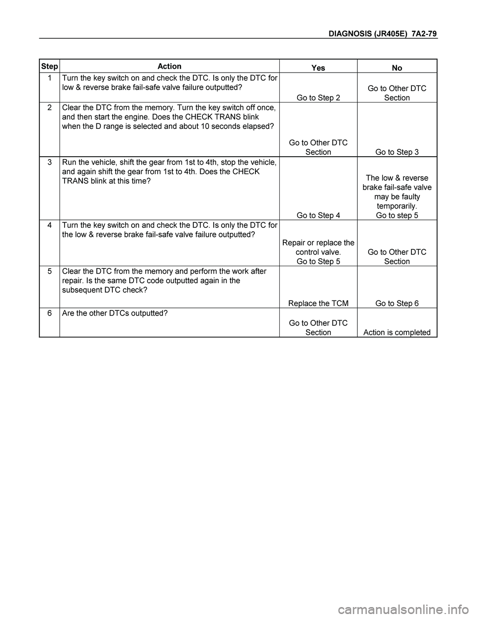
Step Action Yes No
1 Turn the key switch on and check the DTC. Is only the DTC for
low & reverse brake fail-safe valve failure outputted?
Go to Step 2
Go to Other DTC
Section
2 Clear the DTC from the memory. Turn the key switch off once,
and then start the engine. Does the CHECK TRANS blink
when the D range is selected and about 10 seconds elapsed?
Go to Other DTC
Section Go to Step 3
3 Run the vehicle, shift the gear from 1st to 4th, stop the vehicle,
and again shift the gear from 1st to 4th. Does the CHECK
TRANS blink at this time?
Go to Step 4
The low & reverse
brake fail-safe valve
may be faulty
temporarily.
Go to step 5
4 Turn the key switch on and check the DTC. Is only the DTC for
the low & reverse brake fail-safe valve failure outputted?
Repair or replace the
control valve.
Go to Step 5
Go to Other DTC
Section
5 Clear the DTC from the memory and perform the work after
repair. Is the same DTC code outputted again in the
subsequent DTC check?
Replace the TCM Go to Step 6
6 Are the other DTCs outputted?
Go to Other DTC
Section Action is completed
Page 4072 of 4264
7A2-80 DIAGNOSIS (JR405E)
DTC P1755 (Flash Code 52) 2-4 Brake Fail-safe Valve Failure
Control Valve Upper Body2-4 Brake Fail Valve (B)
Control Valve Lower Body2- 4 Br ake Fai l Val ve ( A)
Setting Condition:
� When the oil pressure generated and 2-4 brake pressure switch operates off/on twice, the TCM detected an
operation failure of the low & reverse brake fail-safe valve in D, 3, 2, L range.
Fail Safe:
� When the vehicle is running, the gear position selected at the trouble detection is held and the lock-up is
inhibited.
� After the vehicle stopped, all solenoid operations stop (OFF) and the gear is fixed to the 3rd.
Possible Cause:
� Stick of 2-4 brake fail-safe valve.
� 2-4 brake pressure switch does not turn on.
� Short to ground of harness 2-4 brake pressure switch.
� Faulty fitting of each connector of harness in 2-4 brake pressure switch.
Page 4083 of 4264
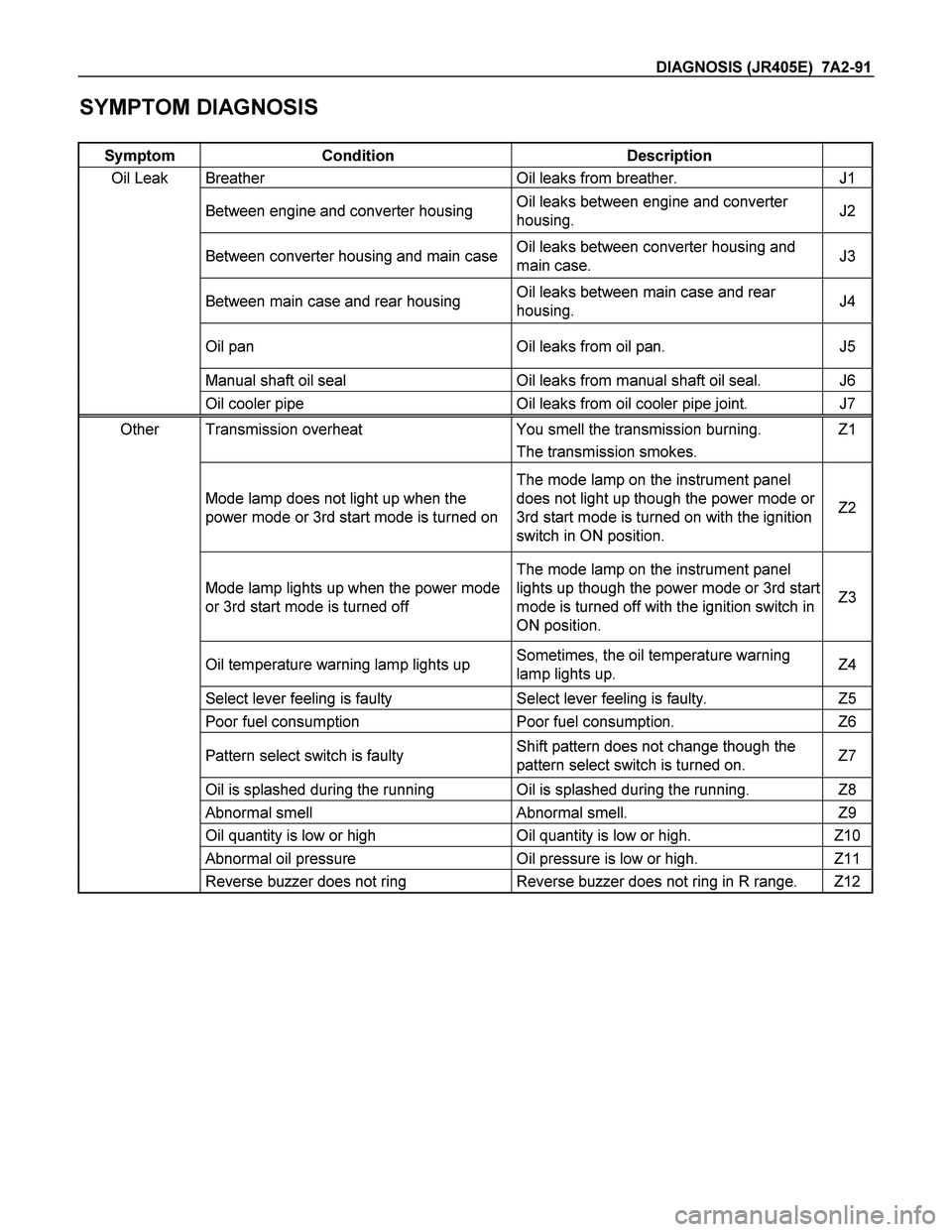
DIAGNOSIS (JR405E) 7A2-91
SYMPTOM DIAGNOSIS
Symptom Condition Description
Oil Leak Breather Oil leaks from breather. J1
Between engine and converter housing Oil leaks between engine and converter
housing. J2
Between converter housing and main caseOil leaks between converter housing and
main case. J3
Between main case and rear housing Oil leaks between main case and rear
housing. J4
Oil pan Oil leaks from oil pan. J5
Manual shaft oil seal Oil leaks from manual shaft oil seal. J6
Oil cooler pipe Oil leaks from oil cooler pipe joint. J7
Other Transmission overheat You smell the transmission burning. Z1
� The transmission smokes.
Mode lamp does not light up when the
power mode or 3rd start mode is turned on
The mode lamp on the instrument panel
does not light up though the power mode or
3rd start mode is turned on with the ignition
switch in ON position.
Z2
Mode lamp lights up when the power mode
or 3rd start mode is turned off
The mode lamp on the instrument panel
lights up though the power mode or 3rd start
mode is turned off with the ignition switch in
ON position.
Z3
Oil temperature warning lamp lights up Sometimes, the oil temperature warning
lamp lights up. Z4
Select lever feeling is faulty Select lever feeling is faulty. Z5
Poor fuel consumption Poor fuel consumption. Z6
Pattern select switch is faulty Shift pattern does not change though the
pattern select switch is turned on. Z7
Oil is splashed during the running Oil is splashed during the running. Z8
Abnormal smell Abnormal smell. Z9
Oil quantity is low or high Oil quantity is low or high. Z10
Abnormal oil pressure Oil pressure is low or high. Z11
Reverse buzzer does not ring Reverse buzzer does not ring in R range. Z12