Page 921 of 4264
ELECTRICAL-BODY AND CHASSIS 8A-263
WARNING LIGHT BULB, INDICATOR
LIGHT BULB AND ILLUMINATION LIGHT
BULB
Removal
Turn the bulb socket counterclockwise and pull the bulb out.
Installation
To Install, follow the removal steps in the reverse order.
FUEL TANK UNIT
Removal
Dismount the fuel tank first, then remove the fuel tank unit.
1. Remove the rear inner liner -LH
� Remove the clip
2. Remove the filler neck.
� Remove the screw
3. Remove the ground with cable.
4. Remove the fuel tank band.
� T/M jack unit on the vehicle.
� Disconnect fuel line quick connectors.
5. Remove the fuel tank unit from the fuel tank.
Page 987 of 4264
ELECTRICAL-BODY AND CHASSIS 8A-329
AUDIO, CLOCK AND CIGARETTE LIGHTER
PARTS LOCATION (RHD)
RTW48AXF020001 & RTW48AXF020101
Page 1076 of 4264
8A-418 ELECTRICAL-BODY AND CHASSIS
CONNECTOR LIST
No. Connector face No. Connector face
B-1
~
B-6 NOT USED B-17
~
B-19 NOT USED
B-7
Black
Rear defogger relay B-20
WhiteCigar lighter illumination
B-8
Black
Power Window Relay B-21
WhiteCigar lighter
B-9
NOT USED B-22
Black
Cigar lighter
B-10
White
Clock B-23
GreenMeter-A
B-11
�
B-12 NOT USED B-24
Green
Meter-B
B-13
White
Fan switch B-25
~
B-27 NOT USED
B-14
Gray
Audio B-24
GreenGround Driver Side
B-15
NOT USED B-30
~
B-29 NOT USED
B-16
White
Hazard switch B-31
SDM
Page 1103 of 4264
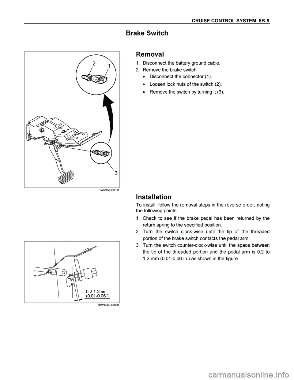
CRUISE CONTROL SYSTEM 8B-5
Brake Switch
RTW3A0MH000101
Removal
1. Disconnect the battery ground cable.
2. Remove the brake switch.
� Disconnect the connector (1).
� Loosen lock nuts of the switch (2).
� Remove the switch by turning it (3).
Installation
To install, follow the removal steps in the reverse order, noting
the following points.
1. Check to see if the brake pedal has been returned by the
return spring to the specified position.
2. Turn the switch clock-wise until the tip of the threaded
portion of the brake switch contacts the pedal arm.
RTW3A0SH000901
3. Turn the switch counter-clock-wise until the space between
the tip of the threaded portion and the pedal arm is 0.2 to
1.2 mm (0.01-0.06 in.) as shown in the figure.
Page 1104 of 4264

8B-6 CRUISE CONTROL SYSTEM
Adjustment
1. Check to be sure that the brake pedal has been completely
returned by the return spring.
2. Disconnect the switch connector.
RTW3A0SH001201
3. Release the lock (2) by turning the switch (1) counter-clock-
wise.
4. After doing so, pull the pedal arm (3) to you a little so tha
t
the pedal arm is not pushed in.
5. Making the pedal arm not movable with one hand, push in
the whole switch with the other hand until the plunger of the
switch is pushed in and the switch itself hits the rubber o
f
the pedal arm.
In the condition, turn the switch clock-wise until "click"
sound is made and lock it.
By doing this, the switch is adjusted at 0.2 to 1.2mm (0.01-
0.06 in.) clearance.
Clutch Switch
Removal and Installation
Refer to the Clutch Control removal and installation steps in
Clutch section.
Adjustment
1. Turn the clutch switch or stopper bolt 1 until the switch bolt
or stopper bolt just touches the clutch pedal arm.
2. Adjust clutch switch or stopper bolt by backing it out half a
turn, and measure the clearance (L) between the clutch
pedal arm and the clutch switch bolt end or stopper bolt.
3. Lock the lock nut
2.
4. Connect the clutch switch connector.
Clutch switch and clutch and clutch pedal clearance
mm (in)
Limit 0.5-1.5 (0.020-0.059)
Starter Switch
431R300001
Removal
1. Steering Lock Assembly
� Refer to the Steering Lock assembly removal steps o
f
"Steering Column" in Power-Assisted Steering System
section.
2. Starter Switch
Installation
Follow the removal procedure in the reverse order to install the
starter switch.
Page 1164 of 4264

6A – 24 ENGINE MECHANICAL
SERVICING
Servicing refers to general maintenance procedures to be performed by qualified service personnel.
RTW36ASH000401
MODEL IDENTIFICATION
Engine Serial Number
The engine number is stamped on the rear left hand side
of the cylinder body.
The engine number is stamped in the plate in front of the
engine room as well.
AIR CLEANER
Element cleaning procedures will vary according to the
condition of the element.
Dust Fouled Element
Rotate the element with your hand while applying
compressed air to the inside of the element. This will blow
the dust free.
Compressed air pressure kPa (kg/cm
2 /psi)
392 – 490 (4 – 5/57 – 71)
LUBRICATING SYSTEM
Main Oil Filter (Cartridge Type Paper Element)
Replacement Procedure
1. Drain the engine oil.
2. Retighten the drain plug.
3. Loosen the used oil filter by turning it counterclockwise
with a filter wrench.
Filter Wrench: 5-8840-0200-0
RTW36ASH000101
4. Clean the oil cooler fitting face. This will allow the new
oil filter to seat properly.
5. Apply a light coat of engine oil to the filter O-ring.
6. Turn in the new oil filter until the filter O-ring is fitted
against the sealing face.
7. Use the filter wrench to turn in the filter an additional
2/3 turns.
8. Check the engine oil level and replenish to the
specified level if required.
130RY00003
6A-6
Page 1165 of 4264

Condition
Model Engine Dry
With oil filter
replacement Without oil
filter
replacement
4 � 2
4 � 4
(4JA1L/TC)6.2")
ENGINE MECHANICAL 6A – 25
Replenished Engine Oil MAX lit (US/UK gal)
Condition
Model Engine Dry
With oil filter
replacement Without oil
filter
replacement
4 � 2
4 � 4
(4JA1L/TC)6.2 (1.64/1.36) 5.2 � 4.2
(1.37 � 1.11
/ 1.14 � 0.92) 4.5 � 3.5
(1.19 � 0.93
/ 0.99 � 0.77)
4 � 2
(4JH1TC)
6.2 (1.64/1.36) 5.2 � 4.2
(1.37 � 1.11
/ 1.14 � 0.92) 4.5 � 3.5
(1.19 � 0.93
/ 0.99 � 0.77)
4 � 4
(4JH1TC) 7.0 (1.85/1.54) 6.2 � 5.2
(1.64 � 1.37
/ 1.36 � 1.14) 5.3 � 4.3
(1.72 � 1.14
/ 1.17 � 0.95)
9. Start the engine and check for oil leakage from the
main oil filter.
6A-7
FUEL SYSTEM
Fuel Filter Replacement Procedure
1. Remove the fuel filter by turning it counterclockwise
with a filter wrench.
Filter Wrench: 5-8840-0253-0 (J-22700)
Note:
Be careful not to spill the fuel in the filter cartridge.
RTW46ASH000501
2. Clean the fuel filter cartridge fitting faces.
This will allow the new fuel filter to seat properly
3. Apply a light coat of engine oil to the O-ring.
4. Turn in the fuel filter until the sealing face comes in
contact with the O-ring.
5. Turn in the fuel filter an additional 2/3 of a turn with a
filter wrench.
Filter Wrench : 5-8840-0253-0 (J-22700)
6. Operate the priming pump until the air discharged
completely from fuel system.
7. Start the engine and check for fuel leakage.
Note:
The use of an ISUZU genuine fuel filter is strongly
recommended.
041RY00009
Page 1174 of 4264

is aligned with the pointer.
Inj")
6A – 34 ENGINE MECHANICAL
RTW46ASH000701
9. Turn the crankshaft clockwise and read the gauge
indication when the crankshaft pulley timing mark (8�)
is aligned with the pointer.
Injection Timing : BTDC 8� � 2�
Standard Reading mm (in)
0.5 (0.02)
If the injection timing is outside the specified range,
continue with the following steps.
10. Loosen the injection pump fixing nuts and bracket
bolts.
11. Adjust the injection pump setting angle.
When large than standard
value When smaller than standard
value
R A
A: Move the injection pump toward the engine.
R: Move the injection pump away from the engine.
ENGINE CONTROL (4JA1T(L) only)
Idling Speed Adjustment
1. Set the vehicle parking brake and chock the drive
wheels.
2. Place the transmission in neutral.
3. Start the engine and allow it to idle until the coolant
temperature reaches 70 - 80�C (158 - 176�F).
4. Disconnect the engine control cable from the control
lever.
5. Set a tachometer to the engine.
6. Check the engine idling speed.
If the engine idling speed is outside the specified
range, it must be adjusted.
Engine Idling Speed : 730 � 25 rpm
Idling Speed Adjustment
1. Loosen the idling set screw lock nut � on the injection
pump idling set bolt.
2. Adjust the idling speed to the specified range by
turning the idling set bolt
�.
3. Lock the engine set nut
� with the idling set bolt lock
nut.
4. Check that the idling control cable is tight (free of
slack). If required, remove the slack from the cable.


RTW48AXF020001 & RTW48AXF020101")