Page 1250 of 4264

6A – 110 ENGINE MECHANICAL
17. Cylinder Body Rear Plate
1. Align the rear plate with the cylinder body knock pins.
2. Tighten the rear plate to the specified torque.
Rear Plate Torque N·m(kg·m/lbft)
82 (8.4/61)
18. Flywheel
1. Apply a coat of engine oil to the threads of the flywheel
bolts.
2. Align the flywheel with the crankshaft dowel pin.
3. Tighten the flywheel bolts in the numerical order shown
in the illustration.
Gear stoper: 5-8840-0214-0
Flywheel Bolt Torque N·m(kg·m/lbft)
118 (12/87)
19. Crankshaft Timing Gear
Use the crankshaft timing gear installer (1) to install the
crankshaft timing gear (2).
The crankshaft timing gear setting mark must be facing
outward.
Crankshaft Timing Gear Installer: 9-8522-0020-0
20. Idler Gear Shaft
21. Idler Gear "A"
1. Turn the crankshaft clockwise to set the DTC of the
No.1 piston.
2. Apply engine oil to the idler gear and the idler gear
shaft.
The idler gear shaft oil hole (A) must be facing up.
3. Position the idler gear setting marks so that they are
facing the front of the engine.
015LX113 020R100001
020RY00034
020RY00035
Page 1340 of 4264
6D – 2 ENGINE ELECTRICAL
MAIN DATA AND SPECIFICATIONS
Description
Item
60A 80A
Generator
Type
AC generator with IC regulator and vacuum pump
Hitachi LR160-503E Hitachi LR180-513B
Voltage V
Drive and rotation
Ground polarity 12
V-belt, clockwise viewed from the drive pulley
Negative
Maximum output A 60 80
Engine speed ratio to 1 1.788
Maximum speed rpm 11,000
Weight with vacuum pump kg(lb) 5.8(12.8) 6.4(14.1)
Vacuum Pump
Delivery volume cm3/rev
Exhaust Characteristic
Maximum vacuum
50
-66.7 kPa (-500 mmHg) bulid up time 21 seconds or less at 1,000
rpm
7 seconds or less at 5,000 rpm
-90.7 kPa (-680 mmHg) or more
Starter Motor
Type
Solenoid controlled
Hitachi S13-555
12
2.3
8.76
300 Rated voltage V
Rated output kW
Load characteristics
Terminal voltage V
Load current A
Weight kg(Ib)
4.7 (10.4)
Page 1366 of 4264
.
Replace the brushes as a set if one or more of the
brush lengths is less")
6D – 28 ENGINE ELECTRICAL
BRUSH AND BRUSH HOLDER
1. Use a vernier caliper to measure the brush length (four
brushes).
Replace the brushes as a set if one or more of the
brush lengths is less than the specified limit.
Brush Length mm (in)
Standard Limit
15 (0.59) 12 (0.47)
RTW46DSH004001
RTW46DSH004101
2. Use a circuit tester to check the brush holder
insulation.
Touch one probe to the holder plate and the other
probe to the positive brush holder.
There should be no continuity.
3. Inspect the brushes for excessive wear.
If the negative brushes have excessive wear, the
entire brush holder assembly must be replaced.
If the positive brushes have excessive wear, the entire
yoke must be replaced.
OVERRUNNING CLUTCH
1. Inspect the overrunning clutch gear teeth for
excessive wear and damage.
Replace the overrunning clutch if necessary.
2. Rotate the pinion clockwise.
It should turn smoothly.
3. Try to rotate the pinion in the opposite direction.
The pinion should lock.
065RY00035
RTW46DSH004401
BEARING
Inspect the bearings for excessive wear and damage.
Replace the bearings if necessary.
Page 1855 of 4264
 6A-31
NOTE: When timing marks are aligned, No.2 piston will
be on Top Dead Center.
014RW003
Legend
(1) Alignment Mark on Oil Pump
(2) Groove on Crankshaft")
ENGINE MECHANICAL (6VE1 3.5L) 6A-31
NOTE: When timing marks are aligned, No.2 piston will
be on Top Dead Center.
014RW003
Legend
(1) Alignment Mark on Oil Pump
(2) Groove on Crankshaft Timing Pulley
(3) Alignment Mark on Crankshaft Timing Pulley
(4) Alignment Mark on Timing Belt
2. Align the alignment mark on the RH bank
camshaft drive gear pulley (2) to the alignmen
t
mark of the cylinder head cover RH (3).
3.
Align the alignment mark (white line) on the
timing belt (1) with alignment mark on the RH
bank camshaft drive gear pulley (2) (on the left
side as viewed from the front of the vehicle)
and put the timing belt on the camshaft drive
gear pulley.
Secure the belt with a double clip or equivalen
t
clip.
014RW00004
Legend
(1) Alignment Mark on Timing Belt (White line).
(2) Alignment Mark on Camshaft Drive Gear Pulley.
(3) Alignemnt Mark on Cylinder Head Cover RH.
4. Align the alignment mark on the LH bank
camshaft drive gear pulley (2) to the alignmen
t
mark of the cylinder head cover LH (3).
5.
Align the alignment mark (white line) on the
timing belt (1) with the alignment mark on the
LH bank camshaft drive gear pulley (2).
When aligning the timing marks, use a wrench
to turn the camshaft drive gear pulley, then se
t
the timing mark between timing belt and
camshaft drive gear pulley and put the timing
belt on the camshaft drive gear pulley.
Secure the belt with a double clip or equivalen
t
clip.
NOTE: It is recommended for easy installation that the
belt be secured with a double clip or equivalent clip afte
r
it is installed the timing belt to each pulley.
014RW00005
Legend
(1) Alignment Mark on Timing Belt (White line).
(2) Alignment Mark on Camshaft Drive Gear Pulley.
(3) Alignemnt Mark on Cylinder Head Cover LH.
6. Install crankshaft pulley temporarily and tighten
center bolt by hand (do not use a wrench).
Turn the crankshaft pulley clockwise to give
some belt slack between the crankshaft timing
pulley and the RH bank camshaft drive gea
r
pulley.
Page 1856 of 4264
6A-32 ENGINE MECHANICAL (6VE1 3.5L)
2. Install pusher and tighten bolt to the specified
torque.
Torque: 25 N�
�� �m (2.5 Kg�
�� �m/18 lb ft)
1. Install the pusher while pushing the tension
pulley to the belt.
2. Pull out pin from the pusher.
NOTE: When reusing the pusher, press the pusher with
approximately 100Kg to retract the rod, and insert a pin
(1.4 mm piano wire).
014RW011
Legend
(1) Up Side
(2) Down Side
(3) Direction for Installation
(4) Locking Pin
3. Remove double clips or equivalent clips, from
timing belt pulleys.
Turn the crankshaft pulley clockwise by two
turns.
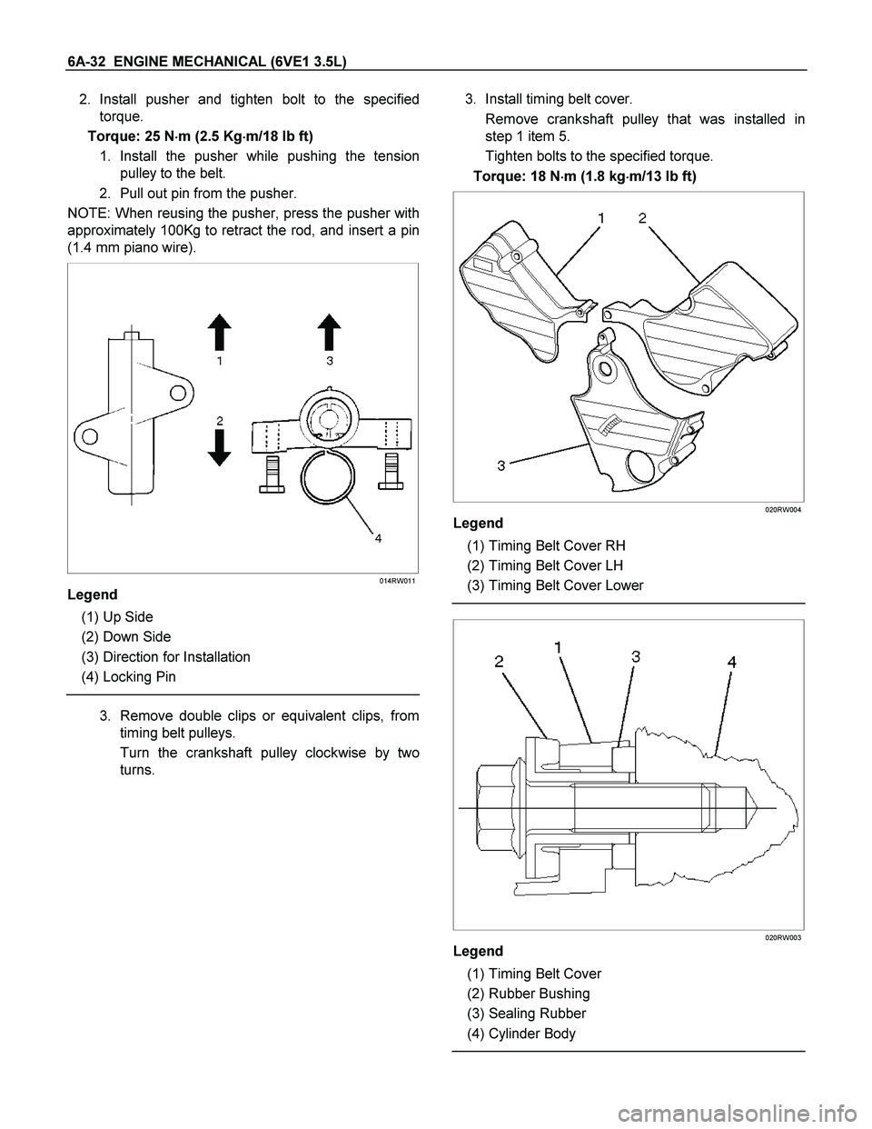
3. Install timing belt cover.
Remove crankshaft pulley that was installed in
step 1 item 5.
Tighten bolts to the specified torque.
Torque: 18 N�
�� �m (1.8 kg�
�� �m/13 lb ft)
020RW004
Legend
(1) Timing Belt Cover RH
(2) Timing Belt Cover LH
(3) Timing Belt Cover Lower
020RW003
Legend
(1) Timing Belt Cover
(2) Rubber Bushing
(3) Sealing Rubber
(4) Cylinder Body
Page 1984 of 4264
6D3-12 STARTING AND CHARGING SYSTEM (6VE1 3.5L)
2. Check continuity between the lead wire of terminal
C and brush.
Replace the yoke assembly, if there is no continuity.
065RY00066
Overrunning Clutch
1. Visual check for excessive wear or damage.
2. Test the pinion rotation, it must rotate smoothly
when rotated clockwise and it shouldn't rotate when
turned counterclockwise.
065RY00067
Bearing
1. Inspect excessive wear or damage.
Replace the bearing if an abnormal noise is heard
under normal operating condition.
065RY00068
Reassembly
To install, follow the removal steps in the reverse order,
noting the following points:
Grease application places
Bearing in rear cover
Gears in reduction gear
Sliding portion of pinion
Page 1985 of 4264
STARTING AND CHARGING SYSTEM (6VE1 3.5L) 6D3-13
Main Data and Specifications
General Specifications
Model ADX4IH
Rating
Voltage 12 V
Output 1.4 Kw
Time 30 sec
Number of teeth of pinion 9
Rotating direction(as viewed from pinion) Clockwise
Weight(approx.) 3.8kg (8.4lb)
No–load characteristics
Voltage /Current 11.5V/90A or less
Speed 3000rpm or more
Load characteristics
Voltage/current 8.5V/350A or less
Torque 13.2Nm (1.35kgm/9.77lb in.) or more
Speed 1000rpm or more
Locking characteristics
Voltage/current 2.4V/500A or less
Torque 11.8N�
�� �m (1.2kg�
�� �m/8.68lb in) or more
Page 1995 of 4264
STARTING AND CHARGING SYSTEM (6VE1 3.5L) 6D3-23
Main Data and Specifications
General Specifications
Parts Number 102211-1740
Model ACJV74
Rated voltage 12 V
Rated output 90 A
Rotating direction (As viewed from pulled) Clockwise
Pulley effective diameter 57.5 mm (2.26 in)
Weight 5.1 kg (11 lb)


2. Check continuity between the lead wire of terminal
C and brush.
Replace the yoke assembly, if there is no continuity.
065RY00066
Overru")
 6D3-13
Main Data and Specifications
General Specifications
Model ADX4IH
Rating
Voltage 12 V
Output 1.4 Kw
Time 30 sec
Number of teeth of pinion")
 6D3-23
Main Data and Specifications
General Specifications
Parts Number 102211-1740
Model ACJV74
Rated voltage 12 V
Rated output 90 A
Rotating direc")