Page 282 of 4264
4C1-62 FRONT WHEEL DRIVE
Important Operations
1. Spacer
Apply grease to both faces of spacer.
4. Inner Assembly
Apply grease wheel bearing to inside face of ring.
g(oz)
Amount of grease 6 (0.21)
7. Knob
(1) Apply grease Wheel bearing to outer circumference of knob
and inner circumference of cover.
(2) Align detent ball to either groove of cover.
8. Snap Ring
Turn the smoother face to knob side.
9. Retaining Spring
Align the end of spring to the end of cut portion of clutch spring
groove.
10. Follower
Install follower to clutch so that follower nail will come closer to
the bent portion of retaining spring by aligning follower stopper
nail to outer teeth of clutch. Then, hook retaining spring onto
upper portion of hanger nails of follower.
11. Compression Spring
Turn the smaller diameter side to follower.
12. Clutch Assembly
Align follower nail to handle groove, and then assemble clutch
with knob by pushing and turning clutch counterclockwise to
knob.
Page 450 of 4264
 Rear wheel cylinder fluid pressure measurement
Step on the brake pedal until the fluid pressure of the
front wheel cylinder gets to 9.8Mpa (100kg/cm
2), and
c")
5C-24 BRAKES
RTW35CSH000201
3) Rear wheel cylinder fluid pressure measurement
Step on the brake pedal until the fluid pressure of the
front wheel cylinder gets to 9.8Mpa (100kg/cm
2), and
check the rear wheel cylinder fluid pressure. (Read the
value of the front wheel cylinder fluid pressure 2
seconds after the measurement. When measuring the
L.S.V fluid pressure, keep the brake pedal pressed
down without stepping it down twice or releasing it.)
Rear Wheel Cylinder Fluid Pressure MPa (kg/cm
2)
2WD 6.77�0.83 (69.0�8.5)
2WD (With High Ride
Suspension), 4WD 6.77�
0.83 (69.0�
8.5)
RTW35CSH000401
2. Oil Pressure Adjustment
1) LSPV spring length adjustment
Loosen the adjust nut of the LSPV spring joint, and
adjust the length of the LSPV spring.
When the oil pressure is insufficient, turn the adjust nu
t
clockwise to extend the span “A”. When the oil pressure
is too high, turn the adjust nut counterclockwise to
reduce the span “A”.
2) After adjustment, tighten the lock nut securely.
Lock Nut Torque N�m (kg�m/lb in)
11-20 (1.1-2.0/95-174)
Page 457 of 4264

BRAKES 5C-31
ADJUSTMENT PROCEDURE OF BRAKE PEDAL
The push rod serves as the brake pedal stopper when the
pedal is fully released.
Brake pedal height adjustment should be performed as follows.
RTW35CSH000601
Brake Pedal - Height
Measure the brake pedal height after making sure the pedal is
fully returned by the pedal return spring.
Note:
Pedal height (L2) must be measured after starting the
engine and increasing the revolution several times by
stepping on the accelerator pedal.
mm(in)
Pedal free play (L1) 6-10 (0.23 - 0.39)
M/T 174-186 (6.85-7.32)
RHD
LHD
A/T 176-188 (6.93-7.40) Height (L2)
Note:
Pedal free play must be measured after turning off the
engine and stepping on the brake pedal firmly five times
or more.
If the measured value deviates from the above range, adjust
the brake pedal as follows:
a) Disconnect the stop lamp switch.
b) Loosen the lock nut on the push rod.
c)
Adjust the brake pedal to the specified height by rotating the
push rod in the appropriate direction.
Lock Nut Torque N�
m(kgf�
m/lb�
�� �
ft)
12 - 18 (1.2 – 1.8 / 9 - 13)
d) Install the stop lamp switch.
Note:
Pedal height (L
2) must be 80 mm (3.14 in.) or more when
applying about 50 kg (110.25 lbs.) of stepping force.
331R300005
How to connect the CLEVICE of BOOSTER ROD with PEDAL
ARM. and how to adjust the PEDAL SW.
After connecting the CLEVIS of BOOSTER ROD with PEDAL
ARM, adjust the PEDAL SW mounted (PDA) to PEDAL
BRACKET by the procedure explained still more bellow.
1. Set the hole of the CLEVIS of BOOSTER&M/CYL ROD
with the hole of the PEDAL ARM.
2. Enter the PIN; PUSH ROD to PEDAL to these holes
from left side of the PEDAL.
3. Enter and fix the PIN; SANP PIN FIX to the DITCH o
f
the PIN; PUSH ROD to PEDAL from right side of the
PEDAL.
4. Release the LOCK by turning the SWITCH counter-
clock-wise.
Page 458 of 4264
5C-32 BRAKES
5. After doing so, pull PEDAL ARM to yourself a little so
that PEDAL ARM is not pushed in.
6. Making PEDAL ARM not movable with one hand, push
in the whole SWITCH with the other hand until the
PLUNGER of SWTCH is pushed in and SWITCH itself
hits the RUBBER of PEDAL ARM.
In the condition, turn SWITCH clock-wise until “click”
sound is made and lock it.
By doing this the SWITCH is adjusted at 0.7�0.5mm
clearance.
Page 539 of 4264
CAB 10-31
13.Ashtray Case
� Pull out the ashtray case.
14. Center Cluster Assembly
1) Pull out the cluster at the 6 clip positions.
2) Disconnect the cigarette lighter, accessory socket,
hazard switch and clock connectors.
15. Control Lever Assembly
�
Remove the 2 fixing screws.
17.Ashtray Bracket
�
Remove the 3 fixing screws and illumination connector.
Caution:
For precautions on installation or removal of SRS-air bag
system, refer to section 9 "Supplemental Restraint System
(SRS) - AIR BAG".
21. Passenger Air Bag
�
Remove 2 fixing bolts, 2 fixing nuts and connector.
22. Side Ventilation Grille.
� Pull out the grilles and disconnect switch connecto
r
(Driver’s side).
23. Vent Duct Assembly/Defroster Nozzle Assembly
�
Refer to section 1 “HVAC” for defroster nozzle and
ventilation duct removal steps.
25. Instrument Panel
�
Remove the clip and 6 fixing bolts.
26. Cross Beam
Page 567 of 4264
CAB 10-59
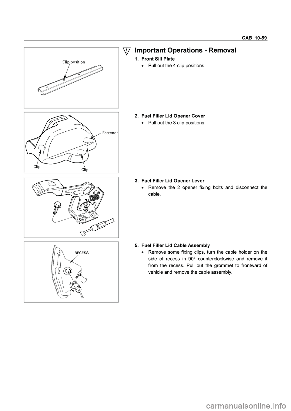
Important Operations - Removal
1. Front Sill Plate
�
Pull out the 4 clip positions.
2. Fuel Filler Lid Opener Cover
�
Pull out the 3 clip positions.
3. Fuel Filler Lid Opener Lever
�
Remove the 2 opener fixing bolts and disconnect the
cable.
5. Fuel Filler Lid Cable Assembly
�
Remove some fixing clips, turn the cable holder on the
side of recess in 90�counterclockwise and remove i
t
from the recess. Pull out the grommet to frontward o
f
vehicle and remove the cable assembly.
Page 570 of 4264
10-62 CAB
Important Operations - Removal
1. Front Sill Plate
�
Pull out 4 clip positions.
2. Rear Sill Plate
�
Pull out 2 clip positions.
4. Fuel Filler Lid Opener Cover
�
Pull out the 3 clip positions.
5. Fuel Filler Lid Opener Lever
�
Remove the 2 opener fixing bolts and disconnect the
cable.
7. Fuel Filler Lid Cable Assembly
�
Remove some fixing clips, turn the cable holder on the
side of recess in 90�counterclockwise and remove i
t
from the recess. Pull out the grommet to frontward o
f
vehicle and remove the cable assembly.
Page 633 of 4264

CLUTCH 7C-31
Driven Plate Splined Hub Spline Wear
1. Clean the driven plate splined hub.
2. Install the driven plate to the transmission top gear shaf
t
spline.
3. Set a surface gauge to the driven plate outside
circumference.
4. Slowly turn the driven plate counterclockwise.
Measure the spline rotation play as you turn the driven
plate.
If the measured value exceeds the specified limit, the driven
plate assembly must be replaced.
Driven Plate Splined Hub Spline Wear mm(in)
Standard Limit
0.5 (0.020) 1.0 (0.039)
Rivet Head Depression
Use a depth gauge or a straight edge with steel rule to
measure the rivet head depression
1 from the facing surface
2.
Be sure to measure the rivet head depression on both sides of
the driven plate.
If the measured value is less than the specified limit, the facing
must be replaced.
Rivet Head Depression mm(in)
Standard
Fly wheel side P/Plate side Limit
4J 1.35-1.95
(0.053-0.077) 1.65-2.25
(0.065-0.089) 0.2
(0.008)
6VE1
C24SE 1.65-2.25
(0.065-0.089) 1.65-2.25
(0.065-0.089) 0.2
(0.008)

Amount of grease")