Page 661 of 4264

ELECTRICAL-BODY AND CHASSIS 8A-3
PAGE
Power Window ........................................................................................................... 8A- 310
Audio, Clock and Cigarette Lighter .......................................................................... 8A- 329
Power Door Mirror ...................................................................................................... 8A- 337
Rear Defogger ............................................................................................................ 8A- 349
SRS-Air Bag ................................................................................................................ 8A- 358
Transfer Case Control Module .................................................................................. 8A- 361
Anti-Lock Brake System ............................................................................................ 8A- 373
Immobilizer ................................................................................................................. 8A- 376
Keyless Entry ............................................................................................................. 8A- 385
Anti Theft ....................................................................................................................8A- 400
Auto Cruise ................................................................................................................. 8A- 412
Trailer Hitch ................................................................................................................ 8A- 415
Connector List ................................................................................................................8A- 418
Page 788 of 4264

8A-130 ELECTRICAL-BODY AND CHASSIS
FRONT TURN LIGHT
Removal
RTW38DSH000601
1. Turn the socket counterclockwise to disconnect it from the
front turn light housing.
2. Pull the bulb from the socket.
Installation
Follow the removal procedure in the reverse order to install the
front turn light.
Pay close attention to the important points mentioned in the
following paragraphs.
Connector
Be absolutely sure that the clearance light connector is
securely connected.
This will prevent a poor contact and an open circuit.
CLEARANCE LIGHT
Removal
RTW38DSH000601
1. Turn the socket counterclockwise to disconnect it from the
clearance light housing.
2. Pull the bulb from the socket.
Installation
Follow the removal procedure in the reverse order to install the
clearance light.
Pay close attention to the important points mentioned in the
following paragraphs.
Connector
Be absolutely sure that the clearance light connector is
securely connected.
This will prevent a poor contact and an open circuit.
Page 800 of 4264
8A-142 ELECTRICAL-BODY AND CHASSIS
FRONT FOG LIGHT
Removal
1. Remove the radiator grille.
2. Remove the front bumper
3. Disconnect the fog light connector.
4. Remove the fog light.
5. Remove the bulb from the socket.
� Remove the socket by turning it counterclockwise.
Installation
Follow the removal procedure in the reverse order to install the
fog light.
Pay close attention to the important points mentioned in the
following paragraphs.
Bulb
Be absolutely sure that the fog light bulb is correctly installed.
This will prevent a poor contact and open circuit.
FRONT FOG LIGHT ADJUSTMENT
Vertical Adjustment
Turn the adjusting screw (1) with a screwdriver to adjust the
aim of the fog light vertically.
RTU4Z0SH000601
FRONT FOG & REAR FOG SWITCH
Page 806 of 4264

8A-148 ELECTRICAL-BODY AND CHASSIS
RTW48ASH000701
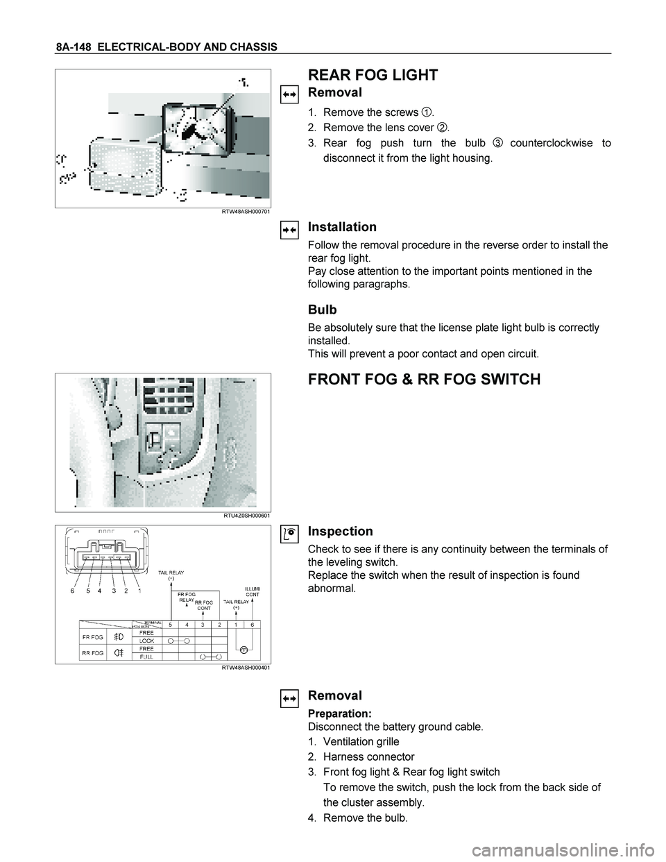
REAR FOG LIGHT
Removal
1. Remove the screws 1.
2. Remove the lens cover
2.
3. Rear fog push turn the bulb
3 counterclockwise to
disconnect it from the light housing.
Installation
Follow the removal procedure in the reverse order to install the
rear fog light.
Pay close attention to the important points mentioned in the
following paragraphs.
Bulb
Be absolutely sure that the license plate light bulb is correctly
installed.
This will prevent a poor contact and open circuit.
RTU4Z0SH000601
FRONT FOG & RR FOG SWITCH
RTW48ASH000401
Inspection
Check to see if there is any continuity between the terminals of
the leveling switch.
Replace the switch when the result of inspection is found
abnormal.
Removal
Preparation:
Disconnect the battery ground cable.
1. Ventilation grille
2. Harness connector
3. Front fog light & Rear fog light switch
To remove the switch, push the lock from the back side of
the cluster assembly.
4. Remove the bulb.
Page 831 of 4264
ELECTRICAL-BODY AND CHASSIS 8A-173
REMOVAL AND INSTALLATION
REAR COMBINATION LIGHT
Stoplight
Removal
1. Open the rear gate.
2. Remove the screws of rear combination light.
3. Remove the rear combination light assembly.
4. Turn the bulb 2 counterclockwise to remove it.
Installation
Follow the removal procedure in the reverse order to install the
rear combination light.
Pay close attention to the important points mentioned in the
following paragraphs.
Bulb
Be absolutely sure that each bulb is correctly installed.
This will prevent a poor contact and an open circuit.
HIGH MOUNTED STOPLIGHT
Remove the bulb socket
1. Remove the high mounted stoplight ASM.
� Remove the screws.
� Disconnect the connector.
2. Remove the bulb socket.
� Turn the bulb
1 counterclockwise to remove it.
Page 832 of 4264

8A-174 ELECTRICAL-BODY AND CHASSIS
Installation
Follow the removal procedure in the reverse order to install the
rear combination light.
Pay close attention to the important points mentioned in the
following paragraphs.
Bulb
Be absolutely sure that each bulb is correctly installed.
This will prevent a poor contact and an open circuit.
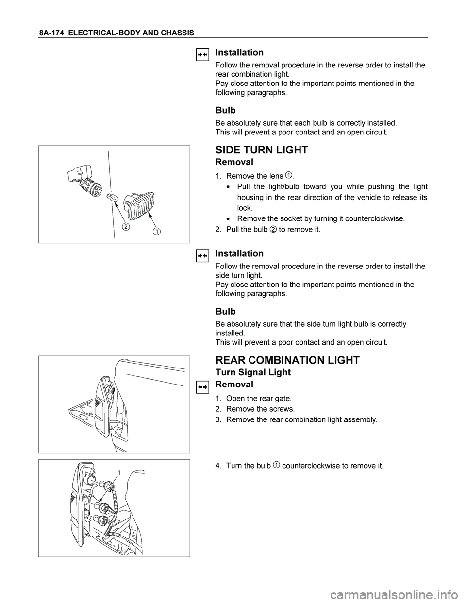
SIDE TURN LIGHT
Removal
1. Remove the lens 1.
� Pull the light/bulb toward you while pushing the ligh
t
housing in the rear direction of the vehicle to release its
lock.
� Remove the socket by turning it counterclockwise.
2. Pull the bulb
2 to remove it.
Installation
Follow the removal procedure in the reverse order to install the
side turn light.
Pay close attention to the important points mentioned in the
following paragraphs.
Bulb
Be absolutely sure that the side turn light bulb is correctly
installed.
This will prevent a poor contact and an open circuit.
REAR COMBINATION LIGHT
Turn Signal Light
Removal
1. Open the rear gate.
2. Remove the screws.
3. Remove the rear combination light assembly.
4. Turn the bulb 1 counterclockwise to remove it.
Page 835 of 4264

ELECTRICAL-BODY AND CHASSIS 8A-177
REAR COMBINATION LIGHT
Back Up Light
Removal
1. Open the rear gate.
2. Remove the screws.
3. Remove the rear combination light assembly.
4. Turn the bulb
3 counterclockwise to remove it.
Installation
Follow the removal procedure in the reverse order to install the
rear combination light.
Pay close attention to the important points mentioned in the
following paragraphs.
Bulbs
Be absolutely sure that each bulb is correctly installed.
This will prevent a poor contact and an open circuit.
This illustration is based on RHD model
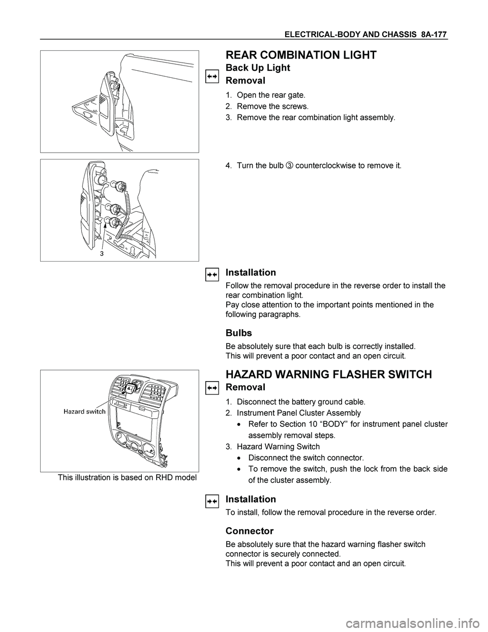
HAZARD WARNING FLASHER SWITCH
Removal
1. Disconnect the battery ground cable.
2. Instrument Panel Cluster Assembly
� Refer to Section 10 “BODY” for instrument panel cluste
r
assembly removal steps.
3. Hazard Warning Switch
� Disconnect the switch connector.
� To remove the switch, push the lock from the back side
of the cluster assembly.
Installation
To install, follow the removal procedure in the reverse order.
Connector
Be absolutely sure that the hazard warning flasher switch
connector is securely connected.
This will prevent a poor contact and an open circuit.
Page 851 of 4264
ELECTRICAL-BODY AND CHASSIS 8A-193
DOOR SWITCH
Removal
1. Disconnect the battery ground cable.
2. Loosen the screw
1.
3. Remove the door switch.
4. Disconnect the door switch connector
3.
Installation
Follow the removal procedure in the reverse order to install the
spot light.
Pay close attention to the important points mentioned in the
following paragraphs.
Connector
Be absolutely sure that the door switch connector is securely
connected.
This will prevent a poor contact and an open circuit.
SPOT LIGHT (MAP Light)
Removal
1. Grasp the spot light housing
1 with both hands.
Pull the housing straight down.
This will release the clip.
2. Disconnect the connector
2.
3. Turn socket
3 counterclockwise to remove it.