Page 3476 of 4264

3B-46 POWER-ASSISTED STEERING SYSTEM
CAUTION:
When turning the SRS coil
counterclockwise to full, stop turning if resistance
is felt. Forced further turning may damage the cable
in the SRS coil.
(with SRS air bag)
826RW014
Legend
(1) Neutral mark
430RX005-X
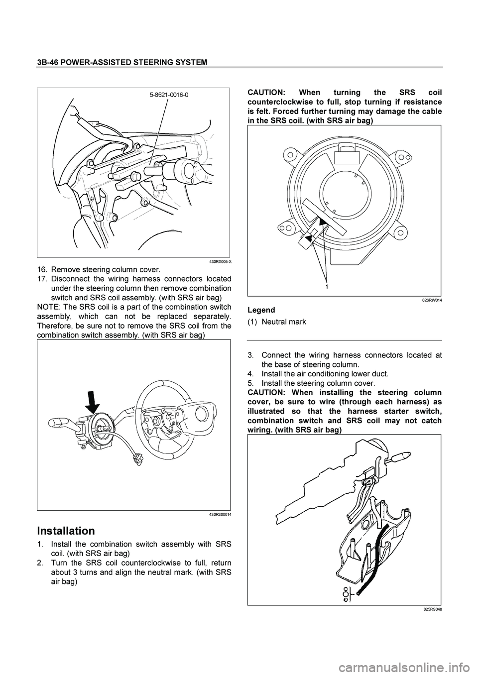
16. Remove steering column cover.
17. Disconnect the wiring harness connectors located
under the steering column then remove combination
switch and SRS coil assembly. (with SRS air bag)
NOTE: The SRS coil is a part of the combination switch
assembly, which can not be replaced separately.
Therefore, be sure not to remove the SRS coil from the
combination switch assembly. (with SRS air bag)
430R300014
Installation
1. Install the combination switch assembly with SRS
coil. (with SRS air bag)
2. Turn the SRS coil counterclockwise to full, return
about 3 turns and align the neutral mark. (with SRS
air bag)
3. Connect the wiring harness connectors located at
the base of steering column.
4. Install the air conditioning lower duct.
5. Install the steering column cover.
CAUTION:
When installing the steering column
cover, be sure to wire (through each harness) as
illustrated so that the harness starter switch,
combination switch and SRS coil may not catch
wiring.
(with SRS air bag)
825RS048
Page 3482 of 4264

3B-52 POWER-ASSISTED STEERING SYSTEM
430R300007
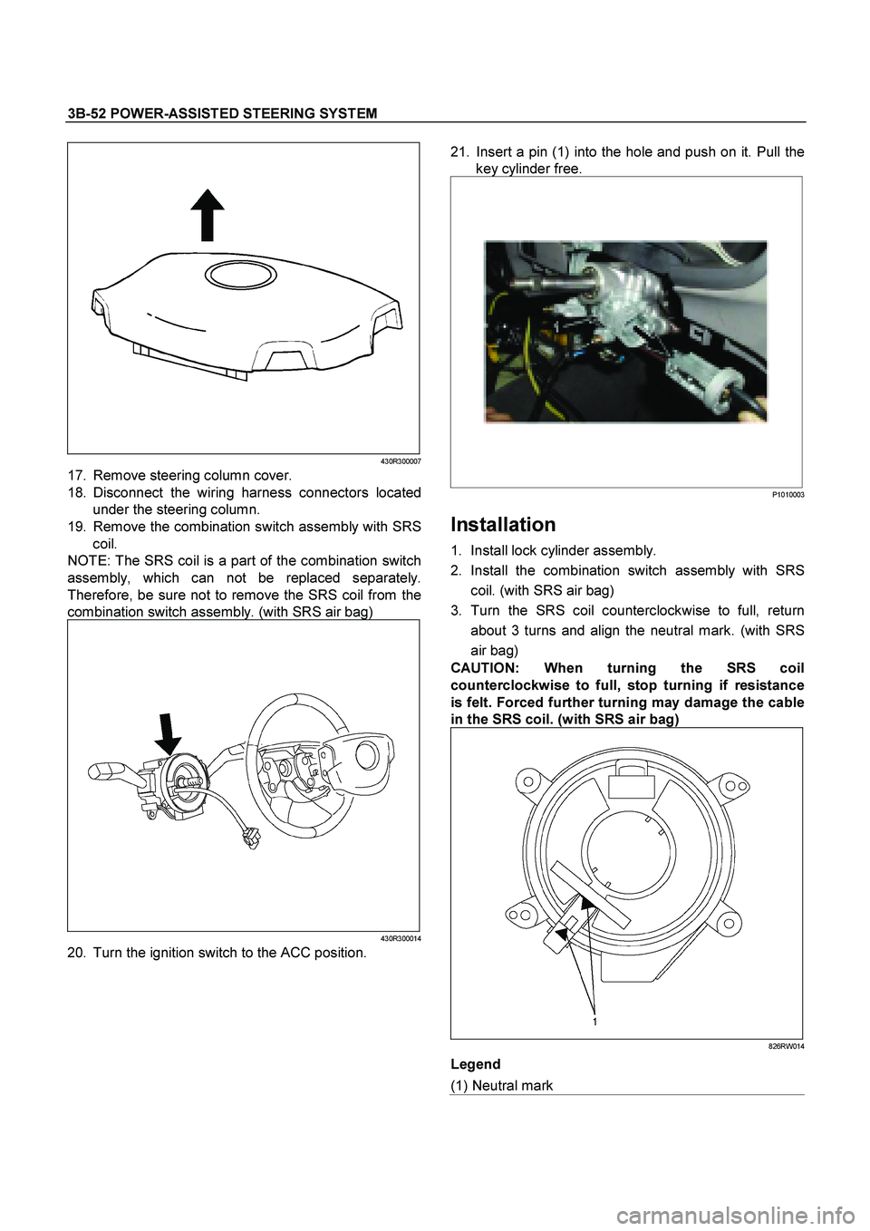
17. Remove steering column cover.
18. Disconnect the wiring harness connectors located
under the steering column.
19. Remove the combination switch assembly with SRS
coil.
NOTE: The SRS coil is a part of the combination switch
assembly, which can not be replaced separately.
Therefore, be sure not to remove the SRS coil from the
combination switch assembly. (with SRS air bag)
430R300014
20. Turn the ignition switch to the ACC position.
21. Insert a pin (1) into the hole and push on it. Pull the
key cylinder free.
P1010003
Installation
1. Install lock cylinder assembly.
2. Install the combination switch assembly with SRS
coil. (with SRS air bag)
3. Turn the SRS coil counterclockwise to full, return
about 3 turns and align the neutral mark. (with SRS
air bag)
CAUTION:
When turning the SRS coil
counterclockwise to full, stop turning if resistance
is felt. Forced further turning may damage the cable
in the SRS coil.
(with SRS air bag)
826RW014
Legend
(1) Neutral mark
Page 3490 of 4264

3B-60 POWER-ASSISTED STEERING SYSTEM
9. Turn the SRS coil counter clockwise to full, return
about 3 turns and align the neutral mark. (with SRS
air bag)
CAUTION: When turning the SRS coil counte
r
clockwise to full, stop turning if resistance is felt.
Forced further turning may damage to the cable in
the SRS coil.
826RW014
10. When installing the steering column cover, be sure to
route each wire harness as illustrated so that the
harnesses do not catch any moving parts.
825RW017
Legend
(1) Steering Column Cover
(2) Starter Switch Harness
(3) Combination Switch Harness
(4) Inflator Module Harness
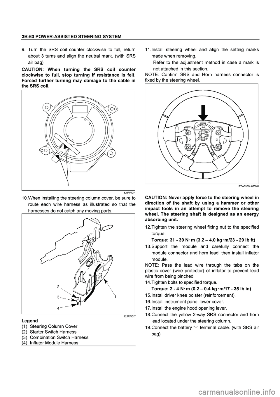
11. Install steering wheel and align the setting marks
made when removing.
Refer to the adjustment method in case a mark is
not attached in this section.
NOTE: Confirm SRS and Horn harness connector is
fixed by the steering wheel.
RTW33BSH000601
CAUTION: Never apply force to the steering wheel in
direction of the shaft by using a hammer or othe
r
impact tools in an attempt to remove the steering
wheel. The steering shaft is designed as an energy
absorbing unit.
12. Tighten the steering wheel fixing nut to the specified
torque.
Torque: 31 - 39 N�
�� �m (3.2 – 4.0 kg�
�� �m/23 - 29 lb ft)
13. Support the module and carefully connect the
module connector and horn lead, then install inflato
r
module.
NOTE: Pass the lead wire through the tabs on the
plastic cover (wire protector) of inflator to prevent lead
wire from being pinched.
14. Tighten bolts to specified torque.
Torque: 2 - 4 N�
�� �m (0.2 – 0.4 kg�
�� �m/17 - 35 lb in)
15. Install driver knee bolster (reinforcement).
16. Install instrument panel lower cover.
17. Install the engine hood opening lever.
18. Connect the yellow 2-way SRS connector and horn
lead located under the steering column.
19. Connect the battery "-" terminal cable. (with SRS ai
r
bag)
Page 3784 of 4264
7A3-28 ON-VEHICLE SERVICE (AW30 –40LE)
Select Lever
RTW37ALF001101
Legend
(6) Base plate
(1) Rear console
(7) Grooved pin
(2) Front console
(8) Spring plate
(3) Select lever knob
(9) Lever assembly
(4) Upper housing
(10) Sleeve
(5) Lamp assembly
Remove or Disconnect
1.
Block the wheels.
2.
Disconnect the negative battery cable.
3.
Remove the rear console and the front console.
4.
Remove the 2 screws fixing the select lever knob.
5.
Remove the knob together with the knob button and
spring from the lever.
6.
Turn the sleeve counterclockwise to remove it. Make
a note of the number of turns required to free the
sleeve.
7.
Remove the harness connectors from the base plate.
Page 3785 of 4264

ON-VEHICLE SERVICE (AW30 –40LE) 7A3-29
8.
Remove the upper housing (held in place by 4
latched fasteners).
9.
Remove the spring plate.
10.
Remove the grooved pin.
11.
Remove the lever assembly by pressing the rod
down (lever in N position).
12.
If lamp replacement is required, remove the lamp
assembly from the lamp socket (align the socke
t
grooved portion and the lamp assembly protruding
portion).
Install or Connect
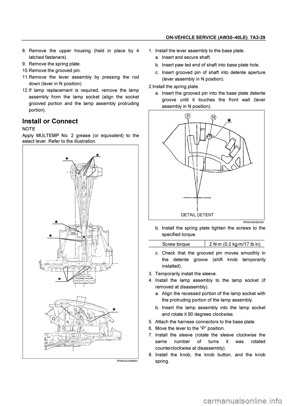
NOTE
Apply MULTEMP No. 2 grease (or equivalent) to the
select lever. Refer to the illustration.
RTW37ALH000201
1.
Install the lever assembly to the base plate.
a.
Insert and secure shaft.
b.
Insert paw led end of shaft into base plate hole.
c.
Insert grooved pin of shaft into detente aperture
(lever assembly in N position).
2.Install the spring plate. a.
Insert the grooved pin into the base plate detente
groove until it touches the front wall (leve
r
assembly in N position).
RTW37ASH001001
b.
Install the spring plate tighten the screws to the
specified torque.
Screw torque 2 N �
m (0.2 kg �
m/17 lb in)
c.
Check that the grooved pin moves smoothly in
the detente groove (shift knob temporaril
y
installed).
3.
Temporarily install the sleeve.
4.
Install the lamp assembly to the lamp socket (i
f
removed at disassembly).
a.
Align the recessed portion of the lamp socket with
the protruding portion of the lamp assembly.
b.
Insert the lamp assembly into the lamp socket
and rotate it 90 degrees clockwise.
5.
Attach the harness connectors to the base plate.
6.
Move the lever to the “P ” position.
7.
Install the sleeve (rotate the sleeve clockwise the
same number of turns it was rotated
counterclockwise at disassembly).
8.
Install the knob, the knob button, and the knob
spring.
Page 3835 of 4264
UNIT REPAIR (AW30–40LE) 7A4–27
8. Install the snap ring.
24 8RY 0 001 4
9. While turning the sun gear input drum clockwise,
install it into the one-way clutch
NOTE: Confirm the thrust washer is installed correctly.
24 8RY 0 002 0
10. Install the front planetary gear and bearing to the
sun gear.
NOTE: Confirm the bearing and race is installed
correctly.
Bearing and race diameter (Reference)
24 7RY 0 0012With wooden blocks under the output shaft, stand
the transmission on the output shaft.
24 7RY 0 0013
Inside Outside
Bearing 35.6 mm (1.40 in) 47.7 mm (1.88 in)
Race 33.7 mm (1.33 in) 47.6 mm (1.87 in)
Page 3852 of 4264
7A4–44 UNIT REPAIR (AW30–40LE)
Disassembly
1. Check operation of one-way clutch.
Hold the OD direct clutch drum and turn the input
shaft.
The input shaft should turn freely clockwise and
should lock counterclockwise.
RUW 37A SH00 450 1
2. Remove OD direct clutch assembly from OD
planetary gear assembly.
2 52L10 000 4
3. Then remove thrust bearing with the race from OD
direct clutch drum.4. Check piston stroke of OD direct clutch (C–0).
Place the oil pump onto the torque converter, and
then place the OD direct clutch assembly onto the
oil pump.
25 2L10 0005Use a dial indicator, measure the OD direct clutch
piston stroke applying and releasing the
compressed air (390 – 780 kPa or 57 – 114 psi) as
shown.
Piston stroke: 1.85 – 2.15 mm (0.0728 – 0.0846 in)
25 2L10 0016
Page 3860 of 4264
7A4–52 UNIT REPAIR (AW30–40LE)
16. Coat the assembled bearing and race with
petroleum jelly and install it with the race side facing
downward.
Bearing and race (Reference)
2 52L10 001 5
17. Align the flukes of discs in the direct clutch.
Install the OD direct clutch assembly onto the OD
planetary gear.
2 52L10 000 4
18. Check operation of one-way clutch
Hold the OD direct clutch drum and turn the input
shaft.
The input shaft should turn freely clockwise and
should lock counterclockwise.
RUW3 7A SH00 4501
E nd OFCa llou t
Inside diameter 28.9 mm (1.138 in)
Outside diameter 50.2 mm (1.976 in)
Legend
(1) Free
(2) Lock