Page 3 of 4264

ACCESSORIES 9-1
SECTION 9
ACCESSORIES
TABLE OF CONTENTS
PAGE
Parts Location ................................................................................................................... 9-2
Circuit Diagram ................................................................................................................. 9-6
Connector List .................................................................................................................. 9-10
Radio .................................................................................................................................. 9-12
Front Speaker .................................................................................................................... 9-13
Tweeter .............................................................................................................................. 9-14
Rear Speaker (Extend Cab)............................................................................................... 9-15
Rear Speaker (Crew Cab) .................................................................................................. 9-16
Clock ................................................................................................................................... 9-17
Antenna ............................................................................................................................. 9-18
Page 12 of 4264
9-10 ACCESSORIES
CONNECTOR LIST
No. Connector face No. Connector face
B-10
White
Clock B-56
WhiteJ/B I4
B-14
Gray
Audio B-62
WhiteIgnition switch
B-20
White
Cigar lighter illumination B-64
SilverWeld splice 1
B-21
White
Cigar lighter B-65
SilverWeld splice 2
B-22
Black
Cigar lighter B-73
SilverWeld splice 3
B-40
Black
Acc socket relay C-2
BlackEngine room –RH ground
B-41
Natural
Acc socket C-108
White
J/B E1
B-42
White
Acc socket C-109
BlackBody –LH ground
B-43
Anti theft control unit D-3
BlackFront speaker -RH
B-55
White
J/B I3 D-8
BlackFront speaker -LH
Page 19 of 4264
ACCESSORIES 9-17
CLOCK
REMOVAL AND INSTALLATION
Removal
1. Remove the center cluster ASM
2. Disconnect the connector.
3. Remove the clock.
Installation
To install, follow the removal steps in the reverse order.
Page 58 of 4264

9A-38 SUPPLEMENTAL RESTRAINT SYSTEM
CAUTION: Never apply force to the steering wheel
in the direction of the shaft by using a hammer o
r
other impact tools in an attempt to remove the
steering wheel. The steering shaft is designed as
an energy absorbing unit.
11. Remove the combination switch assembly with
SRS coil.
NOTE: SRS coil is a part of combination switch
assembly, which cannot be replaced separately.
Therefore, be sure not to remove the SRS coil from
the combination switch assembly.
Installation
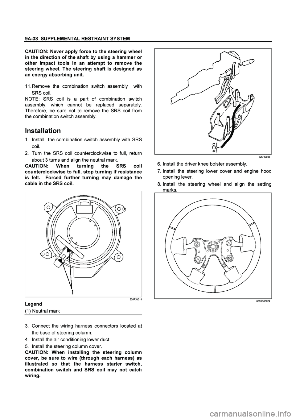
1. Install the combination switch assembly with SRS
coil.
2. Turn the SRS coil counterclockwise to full, return
about 3 turns and align the neutral mark.
CAUTION: When turning the SRS coil
counterclockwise to full, stop turning if resistance
is felt. Forced further turning may damage the
cable in the SRS coil.
826RW014
Legend
(1) Neutral mark
3. Connect the wiring harness connectors located at
the base of steering column.
4. Install the air conditioning lower duct.
5. Install the steering column cover.
CAUTION: When installing the steering column
cover, be sure to wire (through each harness) as
illustrated so that the harness starter switch,
combination switch and SRS coil may not catch
wiring.
825RS048
6. Install the driver knee bolster assembly.
7. Install the steering lower cover and engine hood
opening lever.
8. Install the steering wheel and align the setting
marks.
060R300024
Page 62 of 4264

9A-42 SUPPLEMENTAL RESTRAINT SYSTEM
4. Tighten the universal joint to the specified torque.
Torque: 31 N�
�� �m (3.2 kg�
�� �m/23 lb ft)
5. Install steering lock cylinder assembly.
6. Connect shift lock cable (For A/T)
7. Install cushion rubber.
8. Install snap ring.
9. Install the combination switch assembly with SRS
coil.
10. Connect the wiring harness connector located on
the base of steering column.
11. Turn the SRS coil counterclockwise to full, return
about 3 turns and align the neutral mark.
CAUTION: When turning the SRS coil
counterclockwise to full, stop turning if resistance
is felt. Forced further turning may damage to the
cable in the SRS coil.
826RW014
Legend
(1) Neutral mark
12.Install steering column cover.
CAUTION: When installing the steering column
cover, be sure to wire (through each harness) as
illustrated so that the harness starter switch,
combination switch and SRS coil may not catch
wiring.
825RS048
13.Install the steering wheel and align the setting
marks.
Page 187 of 4264

REAR AXLE 4B-23
c.
Clean the side bearing bores. Place discs and
dial indicator on to arbor, and place tool into
position in side bearing bores. Install and
tighten the bearing caps to the specified
torque.
Torque :
108 N�
m (11 kg�
m/80 lb in)
425RW031
Legend
1.
Dial Indicator : 5-8840-0126-0
2.
Gauge Plate : 5-8840-2166-0
3.
Disc (2 pcs.) : 5-8840-2167-0
4.
Arbor : 5-8840-0128-0
Note :
The scale on the dial indicator (5-8840-0126-0) is
inch unit.
d.
Set the dial indicator 5-8840-0126-0 to “0".
Place it on the mounting post of the gauging
arbor with the contact button touching the
indicator pad. Force the dial indicator
downward until the needle has made a half
turn clockwise. Tighten down the dial
indicator in this position.
425RS020
Legend
1.
Dial Indicator
2.
Gauging Arbor
3.
Plunger
4.
Gauge Plate
e.
Position the plunger on the gauge plate. Move
the gauging arbor slowly back and forth and
locate the position at which the dial indicator
shows the greatest deflection. At this point,
once again set the dial indicator to “0".
Repeat the procedure to verify the “0"
setting.
425RS021
f.
After the ZERO setting is obtained, rotate the
gauging arbor until the dial indicator rod does
not touch the gauging plate. Record the
number the dial indicator needle points to.
Page 255 of 4264

FRONT WHEEL DRIVE 4C1-35
Tighten the nut to the specified torque.
N�m (kgf�m/lb�ft)
New bearing 2.26 (23/20)
Used bearing0.98 - 1.18
(10 - 12/8.7 - 10.4)
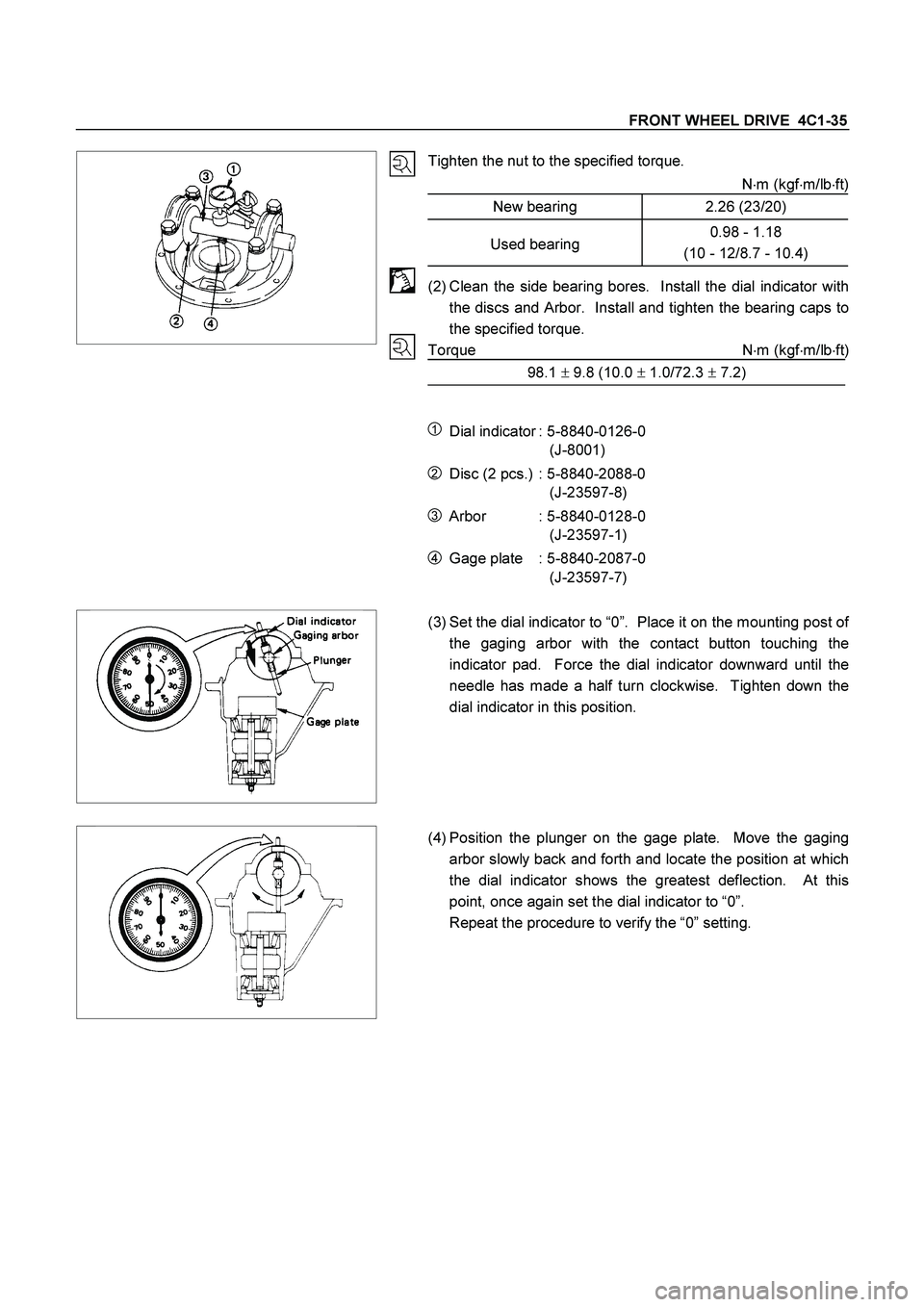
(2) Clean the side bearing bores. Install the dial indicator with
the discs and Arbor. Install and tighten the bearing caps to
the specified torque.
Torque N�
m (kgf�
m/lb�
ft)
98.1 � 9.8 (10.0 � 1.0/72.3 � 7.2)
1 Dial indicator : 5-8840-0126-0
(J-8001)
2 Disc (2 pcs.) : 5-8840-2088-0
(J-23597-8)
3 Arbor : 5-8840-0128-0
(J-23597-1)
4 Gage plate : 5-8840-2087-0
(J-23597-7)
(3) Set the dial indicator to “0”. Place it on the mounting post of
the gaging arbor with the contact button touching the
indicator pad. Force the dial indicator downward until the
needle has made a half turn clockwise. Tighten down the
dial indicator in this position.
(4) Position the plunger on the gage plate. Move the gaging
arbor slowly back and forth and locate the position at which
the dial indicator shows the greatest deflection. At this
point, once again set the dial indicator to “0”.
Repeat the procedure to verify the “0” setting.
Page 278 of 4264
4C1-58 FRONT WHEEL DRIVE
Important Operations
1. Bolt
Before removal, shift transfer lever into “2H” position and set
free wheeling hub knob into “FREE” position.
6. Hub nut
Wrench : 5-8840-2117-0
(J-36827)
7. Hub and disc assembly
Before disassembly, remove the disc brake caliper assembly
and hang it on the frame with wires.
Refer to Section “Brake” for disc brake caliper removal
procedure.
14. Clutch Assembly
While pushing follower knob, turn clutch assembly clockwise
and then remove clutch assembly from knob.
19. Retaining Spring
Remove retaining spring from clutch assembly by turning it
counterclockwise.