Page 2737 of 3502
HEADLAMP - HALOGEN TYPE -
LT-49
C
D
E
F
G
H
I
J
L
MA
B
LT
2. CHECK POWER SUPPLY CIRCUIT
1. Turn ignition switch OFF.
2. Disconnect BCM connector.
3. Check voltage between BCM harness connector and ground.
OK or NG
OK >> GO TO 3.
NG >> Repair harness or connector.
3. CHECK GROUND CIRCUIT
Check continuity between BCM harness connector and ground.
OK or NG
OK >> INSPECTION END
NG >> Repair harness or connector.
CONSULT-II Functions (BCM)BKS001NT
Refer to LT- 1 8 , "CONSULT-II Functions (BCM)" .
CONSULT-II Functions (IPDM E/R)BKS001NU
Refer to LT- 2 0 , "CONSULT-II Functions (IPDM E/R)" .
Terminals Ignition switch position
(+)
(-) OFF ACC ON
BCM
connectorTerminal
M311
GroundApprox. 0 VBattery
voltageBattery
voltage
38 Approx. 0 V Approx. 0 VBattery
voltage
M442Battery
voltageBattery
voltageBattery
voltage
55Battery
voltageBattery
voltageBattery
voltage
PKIA5204E
BCM connector Terminal
GroundContinuity
M4 52 Yes
PKIA6256E
Page 2738 of 3502
LT-50
HEADLAMP - HALOGEN TYPE -
Headlamp High Do Not Illuminate (Both Sides)BKS001NV
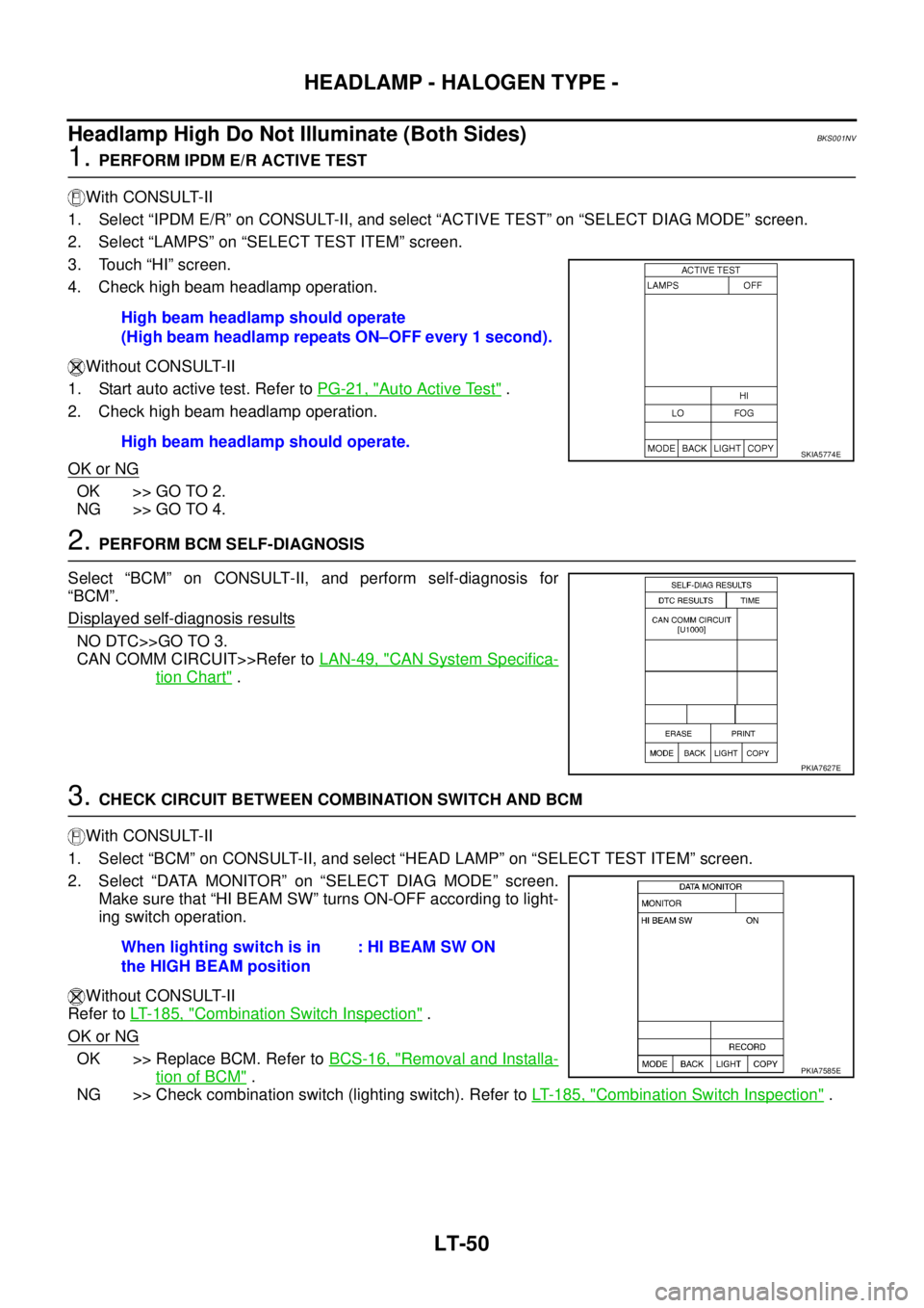
1. PERFORM IPDM E/R ACTIVE TEST
With CONSULT-II
1. Select “IPDM E/R” on CONSULT-II, and select “ACTIVE TEST” on “SELECT DIAG MODE” screen.
2. Select “LAMPS” on “SELECT TEST ITEM” screen.
3. Touch “HI” screen.
4. Check high beam headlamp operation.
Without CONSULT-II
1. Start auto active test. Refer to PG-21, "
Auto Active Test" .
2. Check high beam headlamp operation.
OK or NG
OK >> GO TO 2.
NG >> GO TO 4.
2. PERFORM BCM SELF-DIAGNOSIS
Select “BCM” on CONSULT-II, and perform self-diagnosis for
“BCM”.
Displayed self
-diagnosis results
NO DTC>>GO TO 3.
CAN COMM CIRCUIT>>Refer to LAN-49, "
CAN System Specifica-
tion Chart" .
3. CHECK CIRCUIT BETWEEN COMBINATION SWITCH AND BCM
With CONSULT-II
1. Select “BCM” on CONSULT-II, and select “HEAD LAMP” on “SELECT TEST ITEM” screen.
2. Select “DATA MONITOR” on “SELECT DIAG MODE” screen.
Make sure that “HI BEAM SW” turns ON-OFF according to light-
ing switch operation.
Without CONSULT-II
Refer to LT- 1 8 5 , "
Combination Switch Inspection" .
OK or NG
OK >> Replace BCM. Refer to BCS-16, "Removal and Installa-
tion of BCM" .
NG >> Check combination switch (lighting switch). Refer to LT- 1 8 5 , "
Combination Switch Inspection" . High beam headlamp should operate
(High beam headlamp repeats ON–OFF every 1 second).
High beam headlamp should operate.
SKIA5774E
PKIA7627E
When lighting switch is in
the HIGH BEAM position: HI BEAM SW ON
PKIA7585E
Page 2739 of 3502
HEADLAMP - HALOGEN TYPE -
LT-51
C
D
E
F
G
H
I
J
L
MA
B
LT
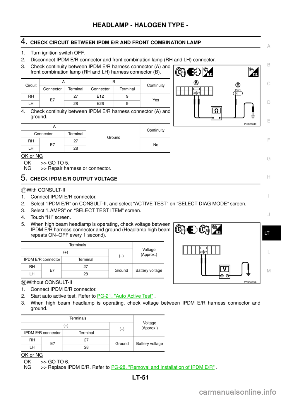
4. CHECK CIRCUIT BETWEEN IPDM E/R AND FRONT COMBINATION LAMP
1. Turn ignition switch OFF.
2. Disconnect IPDM E/R connector and front combination lamp (RH and LH) connector.
3. Check continuity between IPDM E/R harness connector (A) and
front combination lamp (RH and LH) harness connector (B).
4. Check continuity between IPDM E/R harness connector (A) and
ground.
OK or NG
OK >> GO TO 5.
NG >> Repair harness or connector.
5. CHECK IPDM E/R OUTPUT VOLTAGE
With CONSULT-II
1. Connect IPDM E/R connector.
2. Select “IPDM E/R” on CONSULT-II, and select “ACTIVE TEST” on “SELECT DIAG MODE” screen.
3. Select “LAMPS” on “SELECT TEST ITEM” screen.
4. Touch “HI” screen.
5. When high beam headlamp is operating, check voltage between
IPDM E/R harness connector and ground (Headlamp high beam
repeats ON–OFF every 1 second).
Without CONSULT-II
1. Connect IPDM E/R connector.
2. Start auto active test. Refer to PG-21, "
Auto Active Test" .
3. When high beam headlamp is operating, check voltage between IPDM E/R harness connector and
ground.
OK or NG
OK >> GO TO 6.
NG >> Replace IPDM E/R. Refer to PG-28, "
Removal and Installation of IPDM E/R" .
CircuitAB
Continuity
Connector Terminal Connector Terminal
RH
E727 E12 9
Ye s
LH 28 E26 9
A
GroundContinuity
Connector Terminal
RH
E727
No
LH 28
PKID0084E
Terminals
Voltage
(Approx.) (+)
(−)
IPDM E/R connector Terminal
RH
E727
Ground Battery voltage
LH 28
Terminals
Voltage
(Approx.) (+)
(−)
IPDM E/R connector Terminal
RH
E727
Ground Battery voltage
LH 28
PKID0080E
Page 2740 of 3502
LT-52
HEADLAMP - HALOGEN TYPE -
6. CHECK CIRCUIT BETWEEN FRONT COMBINATION LAMP AND GROUND
1. Turn ignition switch OFF.
2. Check continuity between front combination lamp (RH and LH)
harness connector and ground.
OK or NG
OK >> Check headlamp bulb.
NG >> Repair harness or connector.
Front combination lamp
connectorTerminal
GroundContinuity
RH E12 10
Ye s
LH E26 10
PKIA6262E
Page 2741 of 3502
HEADLAMP - HALOGEN TYPE -
LT-53
C
D
E
F
G
H
I
J
L
MA
B
LT
Headlamp High Does Not Illuminate (One Side)BKS001NW
1. CHECK BULB
Check headlamp bulb which does not illuminate.
OK or NG
OK >> GO TO 2.
NG >> Replace headlamp bulb.
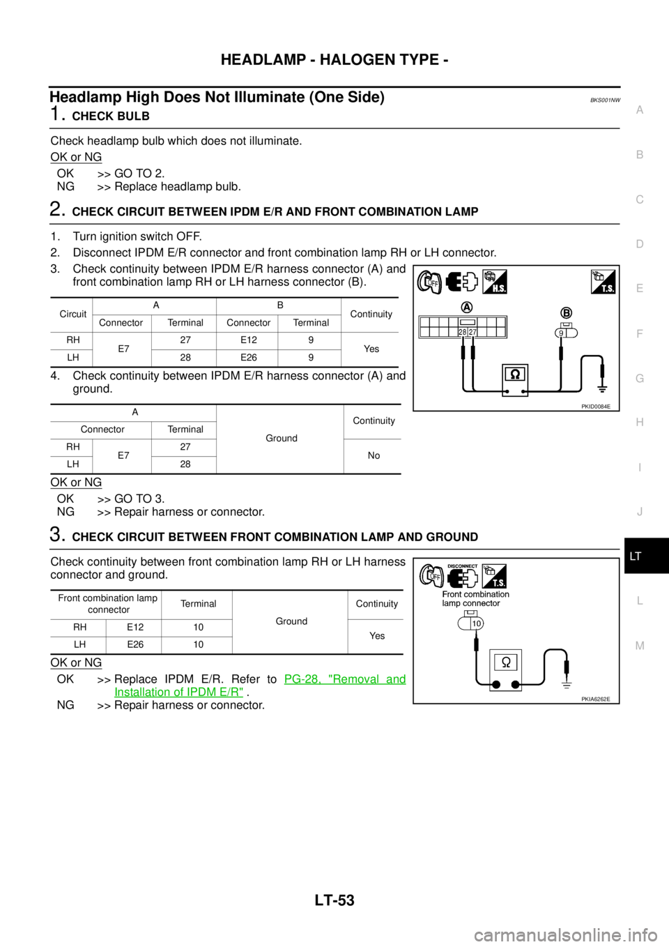
2. CHECK CIRCUIT BETWEEN IPDM E/R AND FRONT COMBINATION LAMP
1. Turn ignition switch OFF.
2. Disconnect IPDM E/R connector and front combination lamp RH or LH connector.
3. Check continuity between IPDM E/R harness connector (A) and
front combination lamp RH or LH harness connector (B).
4. Check continuity between IPDM E/R harness connector (A) and
ground.
OK or NG
OK >> GO TO 3.
NG >> Repair harness or connector.
3. CHECK CIRCUIT BETWEEN FRONT COMBINATION LAMP AND GROUND
Check continuity between front combination lamp RH or LH harness
connector and ground.
OK or NG
OK >> Replace IPDM E/R. Refer to PG-28, "Removal and
Installation of IPDM E/R" .
NG >> Repair harness or connector.
CircuitAB
Continuity
Connector Terminal Connector Terminal
RH
E727 E12 9
Ye s
LH 28 E26 9
A
GroundContinuity
Connector Terminal
RH
E727
No
LH 28
PKID0084E
Front combination lamp
connectorTerminal
GroundContinuity
RH E12 10
Ye s
LH E26 10
PKIA6262E
Page 2742 of 3502
LT-54
HEADLAMP - HALOGEN TYPE -
High Beam Indicator Does Not IlluminateBKS001NX
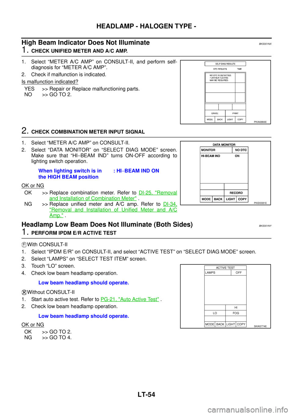
1. CHECK UNIFIED METER AND A/C AMP.
1. Select “METER A/C AMP” on CONSULT-II, and perform self-
diagnosis for “METER A/C AMP”.
2. Check if malfunction is indicated.
Is malfunction indicated?
YES >> Repair or Replace malfunctioning parts.
NO >> GO TO 2.
2. CHECK COMBINATION METER INPUT SIGNAL
1. Select “METER A/C AMP” on CONSULT-II.
2. Select “DATA MONITOR” on “SELECT DIAG MODE” screen.
Make sure that “HI−BEAM IND” turns ON-OFF according to
lighting switch operation.
OK or NG
OK >> Replace combination meter. Refer to DI-25, "Removal
and Installation of Combination Meter" .
NG >> Replace unified meter and A/C amp. Refer to DI-34,
"Removal and Installation of Unified Meter and A/C
Amp." .
Headlamp Low Beam Does Not Illuminate (Both Sides)BKS001NY
1. PERFORM IPDM E/R ACTIVE TEST
With CONSULT-II
1. Select “IPDM E/R” on CONSULT-II, and select “ACTIVE TEST” on “SELECT DIAG MODE” screen.
2. Select “LAMPS” on “SELECT TEST ITEM” screen.
3. Touch “LO” screen.
4. Check low beam headlamp operation.
Without CONSULT-II
1. Start auto active test. Refer to PG-21, "
Auto Active Test" .
2. Check low beam headlamp operation.
OK or NG
OK >> GO TO 2.
NG >> GO TO 4.
PKIA6866E
When lighting switch is in
the HIGH BEAM position: HI−BEAM IND ON
PKID0081E
Low beam headlamp should operate.
Low beam headlamp should operate.
SKIA5774E
Page 2743 of 3502
HEADLAMP - HALOGEN TYPE -
LT-55
C
D
E
F
G
H
I
J
L
MA
B
LT
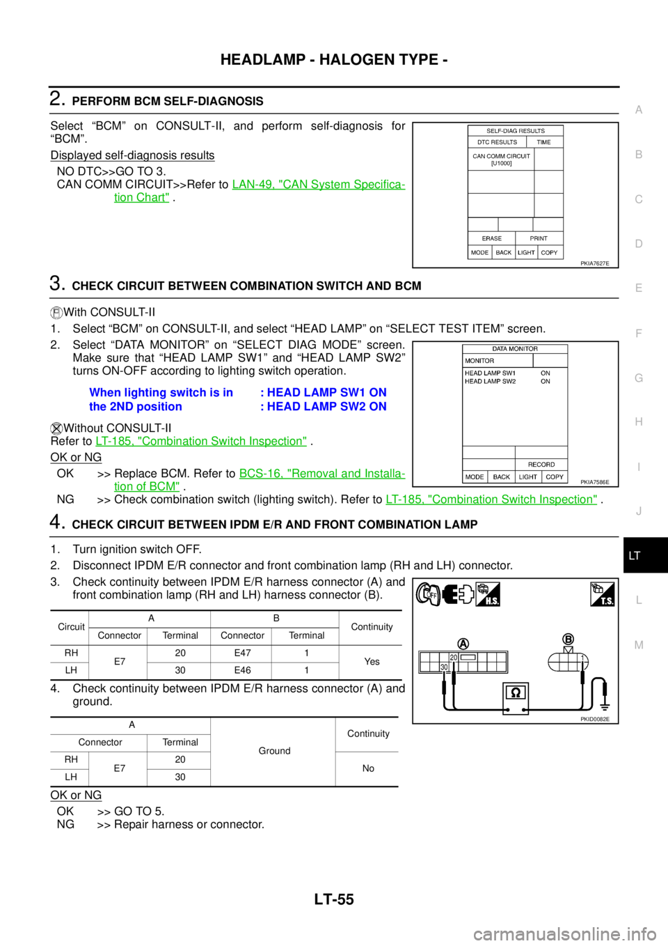
2. PERFORM BCM SELF-DIAGNOSIS
Select “BCM” on CONSULT-II, and perform self-diagnosis for
“BCM”.
Displayed self
-diagnosis results
NO DTC>>GO TO 3.
CAN COMM CIRCUIT>>Refer to LAN-49, "
CAN System Specifica-
tion Chart" .
3. CHECK CIRCUIT BETWEEN COMBINATION SWITCH AND BCM
With CONSULT-II
1. Select “BCM” on CONSULT-II, and select “HEAD LAMP” on “SELECT TEST ITEM” screen.
2. Select “DATA MONITOR” on “SELECT DIAG MODE” screen.
Make sure that “HEAD LAMP SW1” and “HEAD LAMP SW2”
turns ON-OFF according to lighting switch operation.
Without CONSULT-II
Refer to LT- 1 8 5 , "
Combination Switch Inspection" .
OK or NG
OK >> Replace BCM. Refer to BCS-16, "Removal and Installa-
tion of BCM" .
NG >> Check combination switch (lighting switch). Refer to LT- 1 8 5 , "
Combination Switch Inspection" .
4. CHECK CIRCUIT BETWEEN IPDM E/R AND FRONT COMBINATION LAMP
1. Turn ignition switch OFF.
2. Disconnect IPDM E/R connector and front combination lamp (RH and LH) connector.
3. Check continuity between IPDM E/R harness connector (A) and
front combination lamp (RH and LH) harness connector (B).
4. Check continuity between IPDM E/R harness connector (A) and
ground.
OK or NG
OK >> GO TO 5.
NG >> Repair harness or connector.
PKIA7627E
When lighting switch is in
the 2ND position: HEAD LAMP SW1 ON
: HEAD LAMP SW2 ON
PKIA7586E
CircuitAB
Continuity
Connector Terminal Connector Terminal
RH
E720 E47 1
Ye s
LH 30 E46 1
A
GroundContinuity
Connector Terminal
RH
E720
No
LH 30
PKID0082E
Page 2744 of 3502
LT-56
HEADLAMP - HALOGEN TYPE -
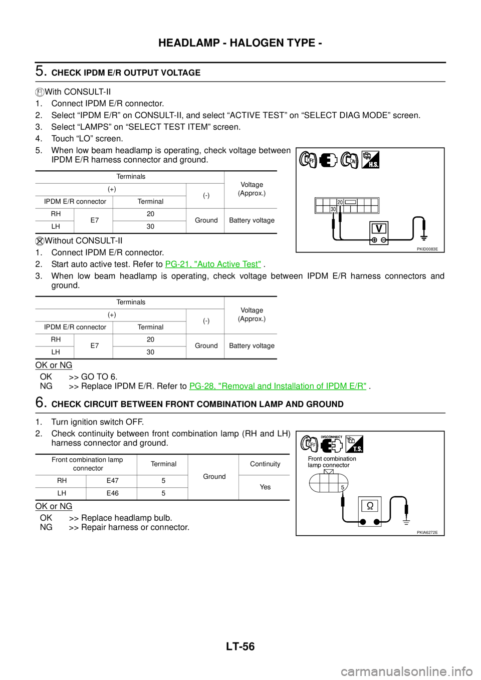
5. CHECK IPDM E/R OUTPUT VOLTAGE
With CONSULT-II
1. Connect IPDM E/R connector.
2. Select “IPDM E/R” on CONSULT-II, and select “ACTIVE TEST” on “SELECT DIAG MODE” screen.
3. Select “LAMPS” on “SELECT TEST ITEM” screen.
4. Touch “LO” screen.
5. When low beam headlamp is operating, check voltage between
IPDM E/R harness connector and ground.
Without CONSULT-II
1. Connect IPDM E/R connector.
2. Start auto active test. Refer to PG-21, "
Auto Active Test" .
3. When low beam headlamp is operating, check voltage between IPDM E/R harness connectors and
ground.
OK or NG
OK >> GO TO 6.
NG >> Replace IPDM E/R. Refer to PG-28, "
Removal and Installation of IPDM E/R" .
6. CHECK CIRCUIT BETWEEN FRONT COMBINATION LAMP AND GROUND
1. Turn ignition switch OFF.
2. Check continuity between front combination lamp (RH and LH)
harness connector and ground.
OK or NG
OK >> Replace headlamp bulb.
NG >> Repair harness or connector.
Terminals
Voltage
(Approx.) (+)
(-)
IPDM E/R connector Terminal
RH
E720
Ground Battery voltage
LH 30
Terminals
Voltage
(Approx.) (+)
(-)
IPDM E/R connector Terminal
RH
E720
Ground Battery voltage
LH 30
PKID0083E
Front combination lamp
connectorTerminal
GroundContinuity
RH E47 5
Ye s
LH E46 5
PKIA6272E