Page 3193 of 4500
Fig. 22: Identifying Waveform 1
Courtesy of TOYOTA MOTOR SALES, U.S.A., INC.
Waveform 2 (Reference):
WAVEFORM 2 REFERENCE TABLE
TerminalIMO - GND
Tool Setting10 V/DIV., 500 ms/DIV.
ConditionNo key in ignition key cylinder -> Key inserted
Page 3194 of 4500
Fig. 23: Identifying Waveform 2
Courtesy of TOYOTA MOTOR SALES, U.S.A., INC.
1.DESCRIPTION
a. The ECM controls the vehicle's immobilizer system functions. Immobilizer system data and the
Diagnostic Trouble Codes (DTCs) can be read through the vehicle's Data Link Connector 3
(DLC3). In some cases, a malfunction may be occurring in the immobilizer system even though the
security indicator lamp is not illuminated. When the system seems to be malfunctioning, use the
hand-held tester to check for malfunctions and perform repairs.
2.CHECK DLC3
HINT:
The vehicle uses the ISO 15765-4 communication protocol. The terminal arrangement of the DLC3
complies with SAE J1962 and matches the ISO 15765-4 format.
Page 3225 of 4500
Fig. 1: Identifying Component Locations
Courtesy of TOYOTA MOTOR SALES, U.S.A., INC.
Page 3226 of 4500

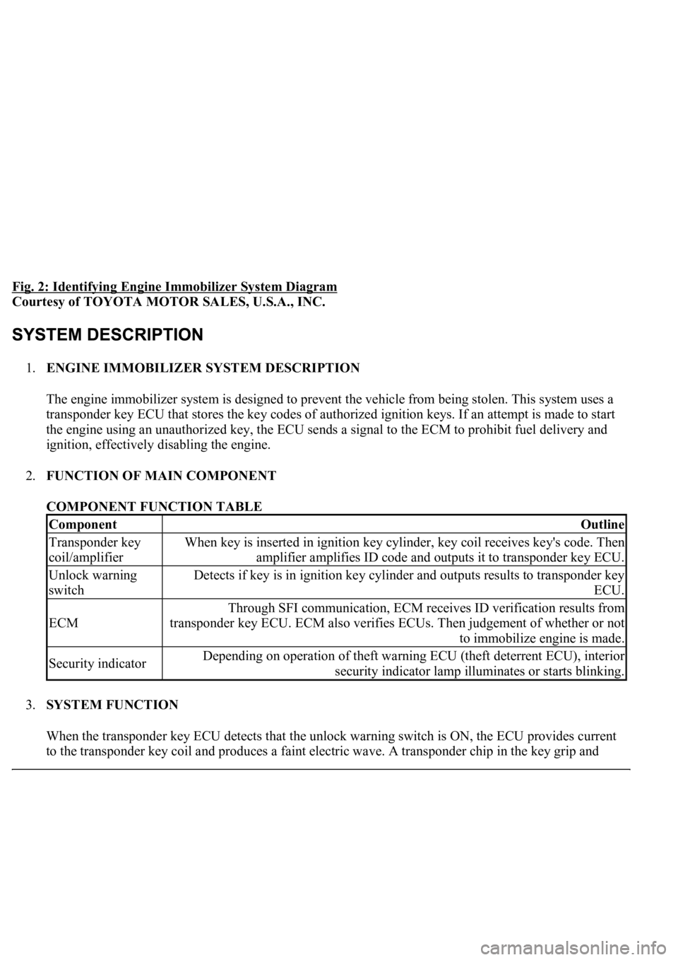
Fig. 2: Identifying Engine Immobilizer System Diagram
Courtesy of TOYOTA MOTOR SALES, U.S.A., INC.
1.ENGINE IMMOBILIZER SYSTEM DESCRIPTION
The engine immobilizer system is designed to prevent the vehicle from being stolen. This system uses a
transponder key ECU that stores the key codes of authorized ignition keys. If an attempt is made to start
the engine using an unauthorized key, the ECU sends a signal to the ECM to prohibit fuel delivery and
ignition, effectively disabling the engine.
2.FUNCTION OF MAIN COMPONENT
COMPONENT FUNCTION TABLE
3.SYSTEM FUNCTION
When the transponder key ECU detects that the unlock warning switch is ON, the ECU provides current
to the transponder ke
y coil and produces a faint electric wave. A transponder chip in the key grip and
ComponentOutline
Transponder key
coil/amplifierWhen key is inserted in ignition key cylinder, key coil receives key's code. Then
amplifier amplifies ID code and outputs it to transponder key ECU.
Unlock warning
switchDetects if key is in ignition key cylinder and outputs results to transponder key
ECU.
ECM
Through SFI communication, ECM receives ID verification results from
transponder key ECU. ECM also verifies ECUs. Then judgement of whether or not
to immobilize engine is made.
Security indicatorDepending on operation of theft warning ECU (theft deterrent ECU), interior
security indicator lamp illuminates or starts blinking.
Page 3229 of 4500
Fig. 4: Identifying Customer Problem Analysis Check
Courtesy of TOYOTA MOTOR SALES, U.S.A., INC.
HINT:
The key has 2 codes: the key code (immobilizer code) and wireless code. All of these code types need to be
registered. Refer to REGISTRATION
for the wireless code registration procedures.
1.DESCRIPTION OF CODE REGISTRATION
Page 3233 of 4500
Fig. 6: Identifying Security Indicator Output Codes
Courtesy of TOYOTA MOTOR SALES, U.S.A., INC.
b. Finish the automatic key code registration mode.
HINT:
The automatic key code registration mode can be forced to end when at least 1 key code
(immobilizer code) for the master key has been registered.
Page 3238 of 4500
Fig. 10: Identifying T8 Amplifier Connector Terminals
Courtesy of TOYOTA MOTOR SALES, U.S.A., INC.
a. Disconnect the T8 amplifier connector.
b. Measure the resistance of the wire harness side connector.
Standard:
TRANSPONDER KEY AMPLIFIER - RESISTANCE TABLE
If the result is not as specified, there may be a malfunction on the wire harness side.
c. Reconnect the T8 amplifier connector.
Symbols (Terminal No.)Wiring ColorTerminal
DescriptionConditionSpecified
Condition
GND (T8-7) - Body
groundV - Body
groundGroundAlwaysBelow 1 ohms
Page 3240 of 4500
Fig. 11: Identifying Waveform 1 Graph
Courtesy of TOYOTA MOTOR SALES, U.S.A., INC.
Waveform 1 (Reference):
WAVEFORM 1 REFERENCE TABLE
Waveform 2 (Reference):
Fig. 12: Identifying Waveform 2 Graph
Courtesy of TOYOTA MOTOR SALES, U.S.A., INC.
WAVEFORM 2 REFERENCE TABLE
TerminalCODE - GND
Tool Setting10 V/DIV., 20 ms/DIV.
ConditionNo key in ignition key cylinder --> Key inserted
TerminalTXCT - GND
Tool Setting5 V/DIV., 20 ms/DIV.
ConditionNo key in ignition key cylinder --> Key inserted